CONTINUOUSLY VARIABLE TRANSAXLE SYSTEM, Diagnostic DTC:P2822
| DTC Code | DTC Name |
|---|---|
| P2822 | Pressure Control Solenoid "J" Electrical (Shift Solenoid Valve SLP) |
DESCRIPTION
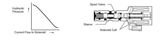
According to current control by the ECM, the shift solenoid valve SLP control primary pulley pressure in accordance with the requested gear ratio to perform gear ratio changes.
| DTC No. | DTC Detection Condition
|
Trouble Area |
|---|---|---|
| P2822 |
|
|
MONITOR DESCRIPTION
When an open or short in the shift solenoid valve SLP circuit is detected, the ECM determines there is a malfunction. The ECM will turn on the MIL and store this DTC.
WIRING DIAGRAM
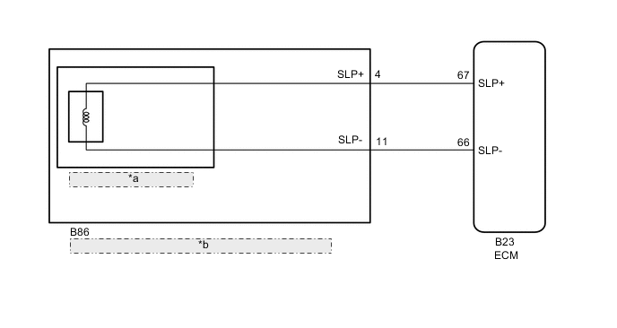
| *a | Shift Solenoid Valve SLP |
| *b | Continuously Variable Transaxle Assembly (Transmission Wire) |
PROCEDURE
-
INSPECT CONTINUOUSLY VARIABLE TRANSAXLE ASSEMBLY (TRANSMISSION WIRE (SHIFT SOLENOID VALVE SLP))
-
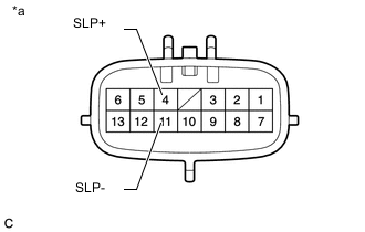
Text In Illustration *a Component without harness connected
(Continuously Variable Transaxle Assembly (Transmission Wire))
Disconnect the transmission wire connector.
-
Measure the resistance according to the value(s) in the table below.
Standard Resistance Tester Connection Condition Specified Condition 4 (SLP+) - 11 (SLP-) 20°C (68°F) 5.0 to 5.6 Ω 4 (SLP+) - Body ground and other terminals Always 10 kΩ or higher 11 (SLP-) - Body ground and other terminals Always 10 kΩ or higher -
Connect the transmission wire connector.
NG 
REPLACE CONTINUOUSLY VARIABLE TRANSAXLE ASSEMBLY Click here
OK 
-
-
CHECK HARNESS AND CONNECTOR
-
Disconnect the ECM connector.
-
Measure the resistance according to the value(s) in the table below.
Standard Resistance Tester Connection Condition Specified Condition B23-67 (SLP+) - B23-66 (SLP-) 20°C (68°F) 5.0 to 5.6 Ω B23-67 (SLP+) - Body ground and other terminals Always 10 kΩ or higher B23-66 (SLP-) - Body ground and other terminals Always 10 kΩ or higher -
Connect the ECM connector.
NG 
REPAIR OR REPLACE HARNESS OR CONNECTOR
OK
-
-
REPLACE ECM
-
Replace the ECM Click here.
NEXT
-
-
PERFORM INITIALIZATION
Note
-
Performing reset memory/initialization will clear the learned value of the deceleration sensor (deceleration sensor zero point calibration) and the CVT oil pressure (CVT oil pressure calibration). Make sure to perform reset memory, deceleration sensor zero point calibration, and CVT oil pressure calibration when replacing any of the parts shown in the following table:
Replaced Part
-
Continuously variable transaxle assembly
-
ECM
-
Brake actuator assembly (Skid control ECU)
-
Oil pressure sensor
-
Deceleration sensor
-
-
After reset memory, always perform deceleration sensor (deceleration sensor zero point) calibration first, and then the CVT oil pressure calibration.
-
Always perform the zero point calibration with the vehicle on level ground.
-
Do not shake or vibrate the vehicle during the zero point calibration.
-
Using the GTS, perform the reset memory, deceleration sensor zero point calibration and CVT oil pressure calibration Click here.
-
Check for DTCs again Click here.
NEXT
END
-
-
REPLACE CONTINUOUSLY VARIABLE TRANSAXLE ASSEMBLY
-
Replace the continuously variable transaxle assembly Click here.
NEXT
-
-
PERFORM INITIALIZATION
Note
-
Performing reset memory/initialization will clear the learned value of the deceleration sensor (deceleration sensor zero point calibration) and the CVT oil pressure (CVT oil pressure calibration). Make sure to perform reset memory, deceleration sensor zero point calibration, and CVT oil pressure calibration when replacing any of the parts shown in the following table:
Replaced Part
-
Continuously variable transaxle assembly
-
ECM
-
Brake actuator assembly (Skid control ECU)
-
Oil pressure sensor
-
Deceleration sensor
-
-
After reset memory, always perform deceleration sensor (deceleration sensor zero point) calibration first, and then the CVT oil pressure calibration.
-
Always perform the zero point calibration with the vehicle on level ground.
-
Do not shake or vibrate the vehicle during the zero point calibration.
-
Using the GTS, perform the reset memory, deceleration sensor zero point calibration and CVT oil pressure calibration Click here.
-
Check for DTCs again Click here.
NEXT
END
-