CONTINUOUSLY VARIABLE TRANSAXLE SYSTEM, Diagnostic DTC:P099B, P099C
| DTC Code | DTC Name |
|---|---|
| P099B | Shift Solenoid "G" Control Circuit Low (Shift Solenoid Valve SC) |
| P099C | Shift Solenoid "G" Control Circuit High (Shift Solenoid Valve SC) |
DESCRIPTION
Based on the signal received by the shift solenoid valve SC, the ECM uses the shift solenoid valve SLU to control the forward and reverse clutch pressure.
If the shift solenoid valve SC has a short or open, the ECM stops sending current to the defective shift solenoid valve.
| DTC No. | DTC Detection Condition
|
Trouble Area |
|---|---|---|
| P099B |
|
|
| P099C |
|
|
MONITOR DESCRIPTION
These DTCs indicate an open or short in the shift solenoid valve SC.
When there is an open or short in the shift solenoid valve SC circuits, the ECM detects the problem and stores the DTC.
WIRING DIAGRAM
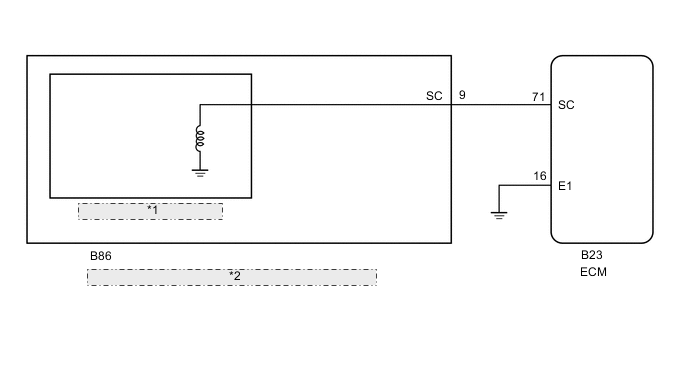
| *1 | Shift Solenoid Valve SC |
| *2 | Continuously Variable Transaxle Assembly (Transmission Wire) |
PROCEDURE
-
INSPECT CONTINUOUSLY VARIABLE TRANSAXLE ASSEMBLY (TRANSMISSION WIRE (SHIFT SOLENOID VALVE SC))
-
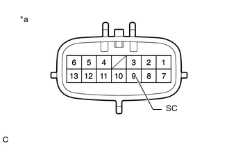
Text in Illustration *a Component without harness connected
(Continuously Variable Transaxle Assembly (Transmission Wire))
Disconnect the transmission wire connector.
-
Measure the resistance according to the value(s) in the table below.
Standard Resistance Tester Connection Condition Specified Condition 9 (SC) - Body ground 20°C (68°F) 11 to 15 Ω -
Connect the transmission wire connector.
NG 
REPLACE CONTINUOUSLY VARIABLE TRANSAXLE ASSEMBLY Click here
OK 
-
-
CHECK HARNESS AND CONNECTOR (TRANSMISSION WIRE - ECM)
-
Disconnect the ECM connector.
-
Measure the resistance according to the value(s) in the table below.
Standard Resistance Tester Connection Condition Specified Condition B23-71 (SC) - Body ground 20°C (68°F) 11 to 15 Ω -
Connect the ECM connector.
NG 
REPAIR OR REPLACE HARNESS OR CONNECTOR
OK
-
-
REPLACE ECM
-
Replace the ECM Click here.
NEXT
-
-
PERFORM INITIALIZATION
Note
-
Performing reset memory/initialization will clear the learned value of the deceleration sensor (deceleration sensor zero point calibration) and the CVT oil pressure (CVT oil pressure calibration). Make sure to perform reset memory, deceleration sensor zero point calibration, and CVT oil pressure calibration when replacing any of the parts shown in the following table:
Replaced Part
-
Continuously variable transaxle assembly
-
ECM
-
Brake actuator assembly (Skid control ECU)
-
Oil pressure sensor
-
Deceleration sensor
-
-
After reset memory, always perform deceleration sensor (deceleration sensor zero point) calibration first, and then the CVT oil pressure calibration.
-
Always perform the zero point calibration with the vehicle on level ground.
-
Do not shake or vibrate the vehicle during the zero point calibration.
-
Using the GTS, perform the reset memory, deceleration sensor zero point calibration and CVT oil pressure calibration Click here.
-
Check for DTCs again Click here.
NEXT
END
-
-
REPLACE CONTINUOUSLY VARIABLE TRANSAXLE ASSEMBLY
-
Replace the continuously variable transaxle assembly Click here.
NEXT
-
-
PERFORM INITIALIZATION
Note
-
Performing reset memory/initialization will clear the learned value of the deceleration sensor (deceleration sensor zero point calibration) and the CVT oil pressure (CVT oil pressure calibration). Make sure to perform reset memory, deceleration sensor zero point calibration, and CVT oil pressure calibration when replacing any of the parts shown in the following table:
Replaced Part
-
Continuously variable transaxle assembly
-
ECM
-
Brake actuator assembly (Skid control ECU)
-
Oil pressure sensor
-
Deceleration sensor
-
-
After reset memory, always perform deceleration sensor (deceleration sensor zero point) calibration first, and then the CVT oil pressure calibration.
-
Always perform the zero point calibration with the vehicle on level ground.
-
Do not shake or vibrate the vehicle during the zero point calibration.
-
Using the GTS, perform the reset memory, deceleration sensor zero point calibration and CVT oil pressure calibration Click here.
-
Check for DTCs again Click here.
NEXT
END
-