CONTINUOUSLY VARIABLE TRANSAXLE SYSTEM, Diagnostic DTC:P0712, P0713
| DTC Code | DTC Name |
|---|---|
| P0712 | Transmission Fluid Temperature Sensor "A" Circuit Low Input |
| P0713 | Transmission Fluid Temperature Sensor "A" Circuit High Input |
DESCRIPTION
The CVT fluid temperature sensor converts the fluid temperature into a resistance value which is input into the ECM.
The sensor resistance changes with the transmission fluid temperature. As the temperature rises, the sensor resistance decreases. The ECM applies a voltage to the temperature sensor through ECM terminal THO1, and the ECM calculates the fluid temperature based on the voltage signal.
Tech Tips
The CVT fluid temperature is likely to increase under conditions such as towing, climbing hills and in heavy traffic.
| DTC No. | DTC Detection Condition
|
Trouble Area |
|---|---|---|
| P0712 |
|
|
| P0713 |
|
|
|
MONITOR DESCRIPTION
The CVT fluid temperature sensor converts the CVT fluid temperature to an electrical resistance value. Based on the resistance, the ECM determines the CVT fluid temperature and detects open or short in the CVT fluid temperature circuit. If the resistance value of the CVT fluid temperature is less than 79 Ω*1 or more than 156 kΩ*2, the ECM interprets this as a fault in the CVT fluid sensor or wiring. The ECM turns on the MIL and stores the DTC.
*1: 150°C (302°F) or more is indicated regardless of the actual CVT fluid temperature.
*2: -40°C (-40°F) is indicated regardless of the actual CVT fluid temperature.
Tech Tips
The CVT fluid temperature can be checked on the GTS display.
WIRING DIAGRAM
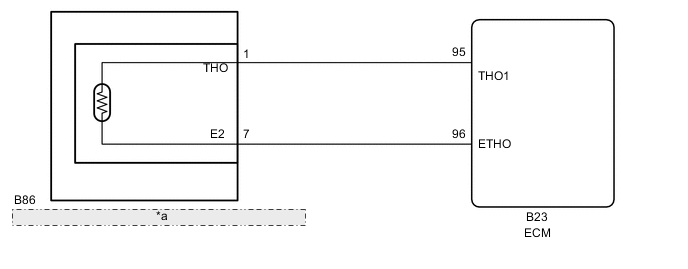
| *a | Continuously Variable Transaxle Assembly (Transmission Wire) |
PROCEDURE
-
INSPECT CONTINUOUSLY VARIABLE TRANSAXLE ASSEMBLY (TRANSMISSION WIRE) (CVT FLUID TEMPERATURE SENSOR)
-
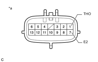
Text in Illustration *a Component without harness connected
(Continuously Variable Transaxle Assembly (Transmission Wire))
Disconnect the transmission wire connector.
-
Measure the resistance according to the value(s) in the table below.
Standard Resistance Tester Connection Condition Specified Condition 1 (THO) - 7 (E2) Always 79 Ω to 156 kΩ 1 (THO) - Body ground Always 10 kΩ or higher 7 (E2) - Body ground Always 10 kΩ or higher Tech Tips
If the resistance is outside the specified range at either of the CVT fluid temperatures shown in the table below, the driveability of the vehicle may be affected.
CVT Fluid Temperature Specified Condition 10°C (50°F) 5.6 to 7.3 kΩ 25°C (77°F) 3.5 kΩ 110°C (230°F) 0.22 to 0.27 kΩ -
Connect the transmission wire connector.
NG 
REPLACE CONTINUOUSLY VARIABLE TRANSAXLE ASSEMBLY Click here
OK 
-
-
CHECK HARNESS AND CONNECTOR (TRANSMISSION WIRE - ECM)
-
Disconnect the ECM connector.
-
Measure the resistance according to the value(s) in the table below.
Standard Resistance Tester Connection Condition Specified Condition B23-95 (THO1) - B23-96 (ETHO) Always 79 Ω to 156 kΩ B23-95 (THO1) - Body ground and other terminals Always 10 kΩ or higher B23-96 (ETHO) - Body ground and other terminals Always 10 kΩ or higher -
Connect the ECM connector.
NG 
REPAIR OR REPLACE HARNESS OR CONNECTOR
OK
-
-
REPLACE ECM
-
Replace the ECM Click here.
NEXT
-
-
PERFORM INITIALIZATION
Note
-
Performing reset memory/initialization will clear the learned value of the deceleration sensor (deceleration sensor zero point calibration) and the CVT oil pressure (CVT oil pressure calibration). Make sure to perform reset memory, deceleration sensor zero point calibration, and CVT oil pressure calibration when replacing any of the parts shown in the following table:
Replaced Part
-
Continuously variable transaxle assembly
-
ECM
-
Brake actuator assembly (Skid control ECU)
-
Oil pressure sensor
-
Deceleration sensor
-
-
After reset memory, always perform deceleration sensor (deceleration sensor zero point) calibration first, and then the CVT oil pressure calibration.
-
Always perform the zero point calibration with the vehicle on level ground.
-
Do not shake or vibrate the vehicle during the zero point calibration.
-
Using the GTS, perform the reset memory, deceleration sensor zero point calibration and CVT oil pressure calibration Click here.
-
Check for DTCs again Click here.
NEXT
END
-
-
REPLACE CONTINUOUSLY VARIABLE TRANSAXLE ASSEMBLY
-
Replace the continuously variable transaxle assembly Click here.
NEXT
-
-
PERFORM INITIALIZATION
Note
-
Performing reset memory/initialization will clear the learned value of the deceleration sensor (deceleration sensor zero point calibration) and the CVT oil pressure (CVT oil pressure calibration). Make sure to perform reset memory, deceleration sensor zero point calibration, and CVT oil pressure calibration when replacing any of the parts shown in the following table:
Replaced Part
-
Continuously variable transaxle assembly
-
ECM
-
Brake actuator assembly (Skid control ECU)
-
Oil pressure sensor
-
Deceleration sensor
-
-
After reset memory, always perform deceleration sensor (deceleration sensor zero point) calibration first, and then the CVT oil pressure calibration.
-
Always perform the zero point calibration with the vehicle on level ground.
-
Do not shake or vibrate the vehicle during the zero point calibration.
-
Using the GTS, perform the reset memory, deceleration sensor zero point calibration and CVT oil pressure calibration Click here.
-
Check for DTCs again Click here.
NEXT
END
-