SHIFT LEVER ASSEMBLY ON-VEHICLE INSPECTION
PROCEDURE
-
INSPECT SHIFT LOCK SOLENOID
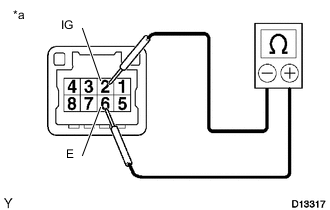
Text in Illustration *a Component without harness connected
(Shift Lock Control Unit Assembly)
-
Disconnect the indicator light wire connector.
-
Measure the resistance according to the value(s) in the table below.
Standard Resistance Tester Connection Condition Specified Condition 2 (IG) - 6 (E) 20 °C (68 °F) 30 to 35 Ω If the resistance is not as specified, replace the shift lock control unit assembly.
-
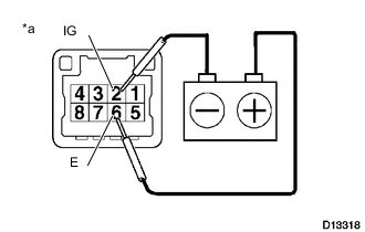
Text in Illustration *a Component without harness connected
(Shift Lock Control Unit Assembly)
Check the solenoid operating sound when applying battery voltage across terminals 2 and 6.
If the solenoid does not operate, replace the shift lock control unit assembly.
-
Connect the indicator light wire connector.
-
-
INSPECT TRANSMISSION SHIFT MAIN SWITCH
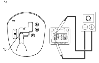
Text in Illustration *a Component without harness connected
(Shift Lock Control Unit Assembly)
*b M Position
-
Disconnect the indicator light wire connector.
-
Move the shift lever to the M position.
-
Measure the resistance according to the value(s) in the table below.
Standard Resistance Tester Connection Condition Specified Condition 4 - 8 M Below 1 Ω -
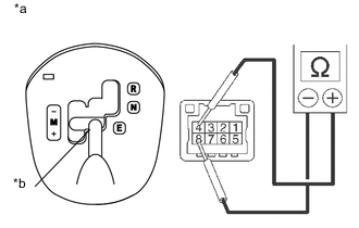
Text in Illustration *a Component without harness connected
(Shift Lock Control Unit Assembly)
*b E Position Move the shift lever to the E position.
-
Measure the resistance according to the value(s) in the table below.
Standard Resistance Tester Connection Condition Specified Condition 4 - 8 E 10 kΩ or higher If the result is not as specified, replace the shift lock control unit assembly.
-
Connect the indicator light wire connector.
-
-
INSPECT SHIFT LEVER POSITION SENSOR
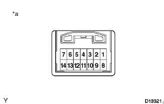
Text in Illustration *a Component without harness connected
(Shift Lever Position Sensor)
-
Disconnect the shift lever position sensor connector.
-
Measure the resistance according to the value(s) in the table below.
Standard Resistance Tester Connection Condition Specified Condition 4 - 9 - 10 - 13 R Below 1 Ω 4 - 2 - 10 - 6 N Below 1 Ω 4 - 2 - 3 - 13 E, M Below 1 Ω 11 - 5 + Below 1 Ω 11 - 5 - 12 M 10 kΩ or higher 11 - 12 - Below 1 Ω If the result is not as specified, replace the shift lock control unit assembly.
-
Connect the shift lever position sensor connector.
-