MULTI-MODE MANUAL TRANSAXLE SYSTEM Multi-Mode Manual Transmission Warning Light Circuit
DESCRIPTION
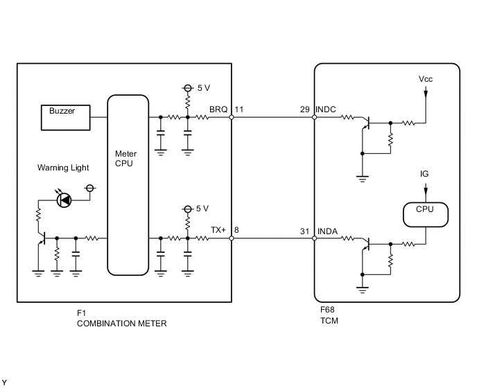
The combination meter interprets the multi-mode manual transaxle system condition according to the information from the INDC and INDA circuits, and if necessary, illuminates (blinks) the multi-mode manual transmission warning light and sounds the buzzer.
-
INDC Terminal Circuit:
The battery voltage is constantly supplied to the INDC circuit. If the INDC circuit is open, the combination meter detects a malfunction in the circuit and illuminates the multi-mode manual transmission warning light. The INDC circuit is used to send the multi-mode manual transmission warning light signal to the combination meter when the ignition switch is off.
-
INDA Terminal Circuit:
Power is supplied to the INDA circuit when the ignition switch is ON. While the ignition switch is ON, the combination meter controls the multi-mode manual transmission warning light ON/OFF condition according to the signal from the INDA circuit. The INDA circuit is used to send the signal for multi-mode manual transmission warning light and shift position indicator to the combination meter.
The contents of signals from the INDC and INDA circuits, and the status of the multi-mode manual transmission warning light, buzzer and indicator are shown in the table below.
| INDA circuit state (at combination meter) | Normal | Inconsistent signal input (3 seconds or more) | Interrupted signal input (3 seconds or more) | |||
| INDC circuit (at combination meter) | Normal | +B short or open | Normal | +B short or open | Normal | +B short or open |
| Shift position indicator *1 |
ON depends on communication signal |
ON depends on communication signal |
OFF | OFF | OFF | OFF |
| Multi-mode manual transmission warning light | ON depends on communication signal |
ON depends on communication signal |
ON | ON | ON | ON |
| Buzzer (Built in combination meter) *2 |
ON | ON | ON | ON | ON | ON |
*1: When shift position indicator ON, the number or letter segments are illuminated.
*2: The buzzer sounds when the following conditions are met in addition to those above.
-
The shift lever is in any position except N.
-
The driver's door is open.
-
Vehicle speed is 9 km/h or less.
-
Engine speed is 400 rpm or more.
| INDA circuit state (at combination meter) | Normal | Inconsistent signal input (3 seconds or more) | Interrupted signal input (3 seconds or more) | |||
| INDC circuit state (at combination meter) | Normal | +B short or open | Normal | +B short or open | Normal | +B short or open |
| Shift position indicator *1 |
ON depends on communication signal |
ON depends on communication signal |
OFF | OFF | OFF | OFF |
| Multi-mode manual transmission warning light | ON depends on communication signal |
ON depends on communication signal |
ON | ON | ON (turns OFF 8 seconds after IG OFF) |
ON |
| Buzzer (Built in combination meter) | OFF | OFF | OFF | ON | OFF | ON |
*1: When shift position indicator ON, the number or letter segments are illuminated.
WIRING DIAGRAM
CAUTION / NOTICE / HINT
Tech Tips
-
Check that the multi-mode manual transmission warning light and shift position indicator light come on.
Under normal conditions, the shift position indicator indicates the current gear position while the ignition switch is turned ON, and the multi-mode manual transmission warning light comes on for bulb check for approximately 5 seconds when the ignition switch is turned from off to ON.
If the shift position indicator light does not come on, the INDA circuit may be malfunctioning. If the multi-mode manual transmission warning light does not come on, the INDA and/or INDC circuits may be malfunctioning.
-
The buzzer built into the combination meter sounds when the following conditions are met.
-
The shift lever is in any position except N.
-
The driver's door is open.
-
Vehicle speed is 10 km/h (6.21 mph) or less.
-
Engine speed is 400 rpm or more.
PROCEDURE
-
CHECK HARNESS AND CONNECTOR (TCM - COMBINATION METER)
-
Disconnect the F68 TCM connector.
-
Disconnect the F1 combination meter connector.
-
Measure the resistance according to the value(s) in the table below.
Standard Resistance Tester Connection Condition Specified Condition F68-29 (INDC) - F1-11 (BRQ) Always Below 1 Ω F68-31 (INDA) - F1-8 (TX+) Always Below 1 Ω F68-29 (INDC) - Body ground Always 10 kΩ or higher F68-31 (INDA) - Body ground Always 10 kΩ or higher
NG 
REPAIR OR REPLACE HARNESS OR CONNECTOR
OK 
-
-
INSPECT COMBINATION METER
-
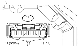
Text In Illustration *a Component with harness connected
(Combination Meter)
Reconnect the F1 combination meter connector.
-
Measure the voltage according to the value(s) in the table below.
Standard Voltage Tester Connection Condition Specified Condition F1-8 (TX+) - Body ground Always 3.64 V or higher F1-11 (BRQ) - Body ground Always 3.64 V or higher
OK
PROCEED TO NEXT SUSPECTED AREA SHOWN IN PROBLEM SYMPTOMS TABLE Click here
NG
GO TO METER / GAUGE SYSTEM Click here
-