MULTI-MODE MANUAL TRANSAXLE SYSTEM Shift Lock Solenoid Circuit
DESCRIPTION
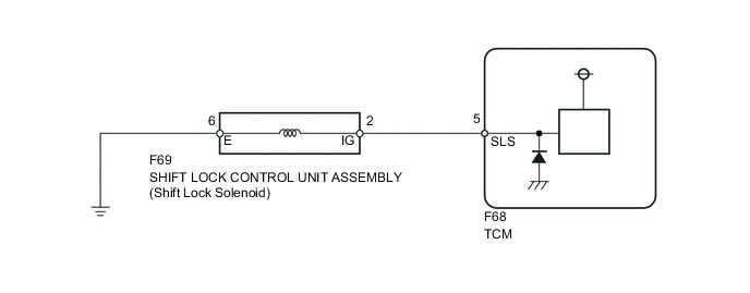
The shift lock solenoid is built into the shift lock control unit assembly. When the ignition switch is turned off, or when the shift lever is in the N position without depressing the brake pedal although the ignition switch is turned to ON, the shift lock solenoid restricts the shift lever movement.
The TCM sends the shift lock cancellation signal to the shift lock solenoid to cancel the shift lock when the multi-mode manual transaxle system conditions are satisfied.
WIRING DIAGRAM
PROCEDURE
-
INSPECT SHIFT LOCK CONTROL UNIT ASSEMBLY (SHIFT LOCK SOLENOID)
-
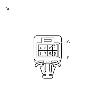
Text In Illustration *a Component without harness connected
(Shift Lock Control Unit Assembly)
Disconnect the F69 shift lock control unit connector.
-
Measure the resistance according to the value(s) in the table below.
Standard Resistance Tester Connection Condition Specified Condition 2 (IG) - 6 (E) 20°C (68°F) 30 to 35 Ω
NG 
REPLACE SHIFT LOCK CONTROL UNIT ASSEMBLY Click here
OK 
-
-
CHECK HARNESS AND CONNECTOR (SHIFT LOCK SOLENOID - TCM, BODY GROUND)
-
Disconnect the F68 TCM connector.
-
Disconnect the F69 shift lock control unit connector.
-
Measure the resistance according to the value(s) in the table below.
Standard Resistance Tester Connection Condition Specified Condition F68-5 (SLS) - F69-2 (IG) Always Below 1 Ω F69-6 (E) - Body ground Always Below 1 Ω F68-5 (SLS) - Body ground Always 10 kΩ or higher
NG
REPAIR OR REPLACE HARNESS OR CONNECTOR
OK
-
-
INSPECT TCM
-
Reconnect the F68 TCM connector.
-
Reconnect the F69 shift lock control unit connector.
-
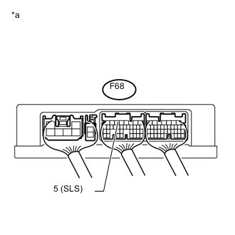
Text In Illustration *a Component with harness connected
(TCM)
Turn the ignition switch to ON.
-
Measure the voltage according to the value(s) in the table below.
Standard Voltage Tester Connection Pedal Condition Specified Condition F68-5 (SLS) - Body ground Brake pedal depressed 11 to 14 V F68-5 (SLS) Body ground Brake pedal released Below 1 V
OK
PROCEED TO NEXT SUSPECTED AREA SHOWN IN PROBLEM SYMPTOMS TABLE Click here
NG
-
-
REPLACE TCM
-
Replace the TCM Click here.
NEXT
-
-
PERFORM INITIALIZATION
-
Perform the initialization and learning for multi-mode manual transaxle system Click here.
NEXT
END
-