MULTI-MODE MANUAL TRANSAXLE SYSTEM Shift Paddle Switch Circuit
DESCRIPTION
Moving the shift lever to the M or E position enables the gear selection. The drive can select gears optionally by shifting the paddle to the [+] or [-].
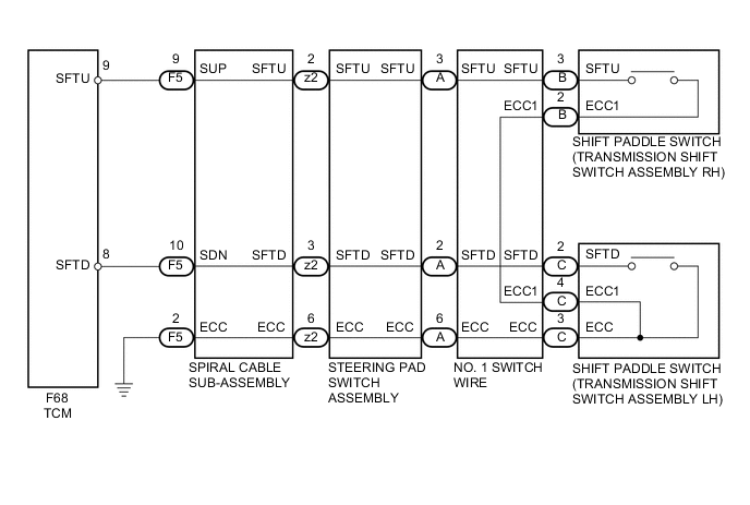
WIRING DIAGRAM
PROCEDURE
-
CHECK HARNESS AND CONNECTOR (SHIFT PADDLE SWITCH - TCM)
-
Disconnect the F68 TCM connector.
-
Measure the resistance according to the value(s) in the table below.
Standard Resistance Tester Connection Condition Specified Condition F68-9 (SFTU) - Body ground Pull continuously "+" (up shift) Below 1 Ω Release "+" (up shift) 10 kΩ or higher F68-8 (SFTD) - Body ground Pull continuously "-" (down shift) Below 1 Ω Release "-" (down shift) 10 kΩ or higher
NG 
CHECK HARNESS AND CONNECTOR (SPIRAL CABLE SUB-ASSEMBLY - TCM) Click here
OK 
-
-
REPLACE TCM
-
Replace the TCM Click here.
NEXT
-
-
PERFORM INITIALIZATION
-
Perform the initialization and learning for multi-mode manual transaxle system Click here.
NEXT 
END
-
-
CHECK HARNESS AND CONNECTOR (SPIRAL CABLE SUB-ASSEMBLY - TCM)
-
Disconnect the F5 spiral cable sub-assembly connector.
-
Disconnect the F68 TCM connector.
-
Measure the resistance according to the value(s) in the table below.
Standard Resistance (Check for Open) Tester Connection Switch Condition Specified Condition F5-9 (SUP) - F68-9 (SFTU) Always Below 1 Ω F5-10 (SDN) - F68-8 (SFTD) Always Below 1 Ω F5-2 (ECC) - Body ground Always Below 1 Ω Standard Resistance (Check for Short) Tester Connection Switch Condition Specified Condition F5-9 (SUP) - Body ground Always 10 kΩ or higher F5-10 (SDN) - Body ground Always 10 kΩ or higher F68-9 (SFTU) - Body ground Always 10 kΩ or higher F68-8 (SFTD) - Body ground Always 10 kΩ or higher
NG
REPAIR OR REPLACE HARNESS OR CONNECTOR
OK
-
-
INSPECT SPIRAL CABLE SUB-ASSEMBLY
-
Disconnect the F5 and z2 spiral cable sub-assembly connector.
-
Measure the resistance according to the value(s) in the table below.
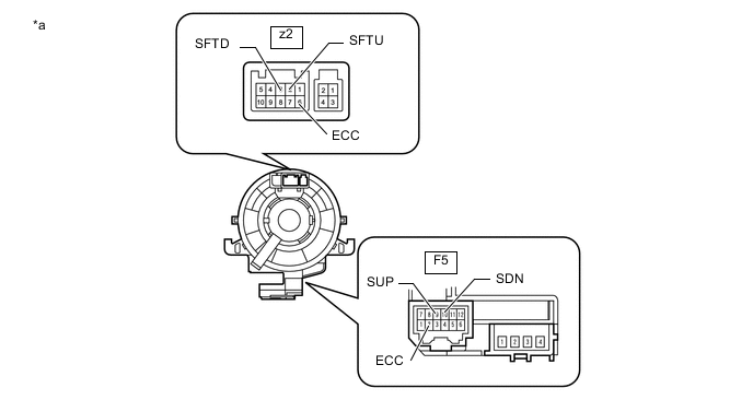
Standard Resistance Tester Connection Condition Specified Condition F5-2 (ECC) - z2-6 (ECC) Always Below 1 Ω F5-9 (SUP) - z2-2 (SUP) Always Below 1 Ω F5-10 (SDN) - z2-3 (SDN) Always Below 1 Ω Text In Illustration *a Component without harness connected
(Spiral Cable Sub-assembly)
NG
REPLACE SPIRAL CABLE SUB-ASSEMBLY Click here
OK
-
-
INSPECT SHIFT PADDLE SWITCH (TRANSMISSION SHIFT SWITCH ASSEMBLY)
-
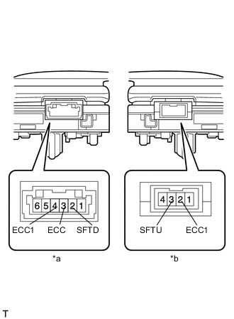
Text In Illustration *a Component without harness connected
(Shift Paddle Switch (Transmission Shift Switch Assembly LH))
*b Component without harness connected
(Shift Paddle Switch (Transmission Shift Switch Assembly RH))
Disconnect the shift paddle switch (transmission shift switch assembly) connector.
-
Measure the resistance according to the value(s) in the table below.
Standard Resistance for RH Tester Connection Switch Condition Specified Condition 3 (SFTU) - 2 (ECC1) Pull continuously "+" (Up shift) Below 2.5 Ω Release "+" (Up shift) 1 MΩ or higher for LH Tester Connection Switch Condition Specified Condition 2 (SFTD) - 3 (ECC) Pull continuously "-" (Down shift) Below 2.5 Ω Release "-" (Down shift) 1 MΩ or higher 2 (SFTD) - 4 (ECC1) Pull continuously "-" (Down shift) Below 2.5 Ω Release "-" (Down shift) 1 MΩ or higher
NG
REPLACE SHIFT PADDLE SWITCH (TRANSMISSION SHIFT SWITCH ASSEMBLY) Click here
OK
-
-
INSPECT STEERING PAD SWITCH ASSEMBLY
-
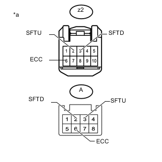
Text In Illustration *a Component without harness connected
(Steering pad switch assembly)
Disconnect the z2 steering pad switch assembly connectors.
-
Measure the resistance according to the value(s) in the table below.
Standard Resistance Tester Connection Condition Specified Condition z2-2 (SFTU) - A-3 (SFTU) Always Below 2.5 Ω z2-3 (SFTD) - A-2 (SFTD) Always Below 2.5 Ω z2-6 (ECC) - A-6 (ECC) Always Below 2.5 Ω
OK
REPLACE NO. 1 SWITCH WIRE Click here
NG
REPLACE STEERING PAD SWITCH ASSEMBLY Click here
-