MULTI-MODE MANUAL TRANSAXLE SYSTEM, Diagnostic DTC:P0500
| DTC Code | DTC Name |
|---|---|
| P0500 | Vehicle Speed Sensor "A" |
DESCRIPTION
Vehicles, which are equipped with the VSC (Vehicle Stability Control System), detect the vehicle speed using the skid control ECU and wheel speed sensor. The wheel speed sensor monitors the wheel rotation speed and sends a signal to the skid control ECU. The skid control ECU converts the wheel speed signal into a 4-pulse signal and transmits it to the TCM via the combination meter. The TCM determines the vehicle speed based on the frequency of the pulse signal.
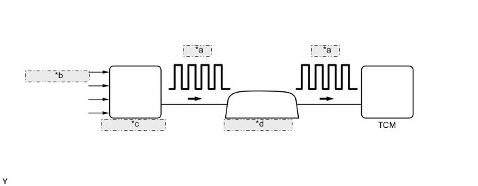
| *a | 4-pulse |
| *b | From Wheel Speed Sensor |
| *c | Skid Control ECU |
| *d | Combination Meter |
| DTC No. | DTC Detection Condition | Trouble Area |
|---|---|---|
| P0500 | The TCM detects the following conditions simultaneously for 4 seconds or more: (1-trip detection logic)
|
|
WIRING DIAGRAM
Refer to METER/GAUGE system Click here.
Tech Tips
When a DTC P0500 is output, a ground short in the wiring of terminal SPD or an internal ground short in the relevant ECU is suspected.
PROCEDURE
-
READ VALUE USING INTELLIGENT TESTER (VEHICLE SPEED)
-
Connect the intelligent tester to the DLC3.
-
Turn the ignition switch to ON.
-
Turn the tester on.
-
Enter the following menu items: Powertrain / Multi-Mode M/T / Data List / Vehicle Speed.
-
Drive the vehicle.
-
Read the value displayed on the tester.
OK Vehicle speeds displayed on tester and speedometer display are equal.
OK 
SYMPTOM SIMULATION AND DTC CHECK Click here
NG 
-
-
CHECK COMBINATION METER ASSEMBLY (SPD SIGNAL WAVEFORM)
-
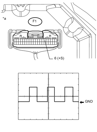
Text In Illustration *a Component with harness connected
(Combination Meter Assembly)
Check the output waveform.
-
Remove the combination meter assembly with the connector(s) still connected.
-
Connect an oscilloscope to terminals F1-6 (+S) and body ground.
-
Turn the ignition switch to ON.
-
Turn the wheel slowly.
-
Check the signal waveform according to the condition(s) in the table below.
Item Condition Tool setting 5 V/DIV., 20 ms/DIV. Vehicle condition Driving at approx. 20 km/h (12 mph) OK The waveform is displayed as shown in the illustration. Tech Tips
When the system is functioning normally, one wheel revolution generates 4 pulses. As the vehicle speed increases, the width indicated by (A) in the illustration narrows.
-
NG
GO TO METER / GAUGE SYSTEM (SPEED SIGNAL CIRCUIT) Click here
OK
-
-
CHECK HARNESS AND CONNECTOR (TCM - COMBINATION METER)
-
Disconnect the A47 TCM connector.
-
Disconnect the F1 combination meter connector.
-
Measure the resistance according to the value(s) in the table below.
Standard resistance (Check for open) Tester Connection Condition Specified Condition F1-6 (+S) - A47-23 (SPD) Always Below 1 Ω -
Reconnect the A47 TCM connector.
-
Reconnect the F1 combination meter connector.
NG
REPAIR OR REPLACE HARNESS OR CONNECTOR (TCM - COMBINATION METER)
OK
-
-
REPLACE TCM
-
Replace the TCM Click here.
NEXT
-
-
PERFORM INITIALIZATION
-
Perform the initialization and learning for multi-mode manual transaxle system Click here.
NEXT
END
-