MULTI-MODE MANUAL TRANSAXLE SYSTEM, Diagnostic DTC:P0703
| DTC Code | DTC Name |
|---|---|
| P0703 | Brake Switch "B" Circuit |
DESCRIPTION
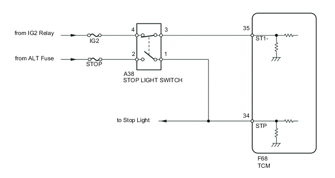
When the brake pedal is depressed, stop light switch signal STP turns on and stop light switch signal ST1- turns off. The TCM detects whether the brake pedal is depressed or released using those signal input. If the signal conditions, STP and ST1-, do not match the standard condition, the TCM interprets this as a malfunction in the stop light switch circuit and sets the DTC.
| DTC No. | DTC Detection Condition | Trouble Area |
|---|---|---|
| P0703 | Following conditions detected simultaneously for 1.0 second or more (1-trip detection logic)
|
|
WIRING DIAGRAM
CAUTION / NOTICE / HINT
Note
Inspect the fuses for circuits related to this system before performing the following inspection procedure.
PROCEDURE
-
READ VALUE USING INTELLIGENT TESTER (BRAKE SWITCH SIGNAL 1 AND 2)
-
Connect the intelligent tester to the DLC3.
-
Turn the ignition switch to ON.
-
Turn the tester on.
-
Enter the following menus: Powertrain / Multi-Mode M/T / Data List / Brake Switch Signal1, Brake Switch Signal2 and STP Switch Signal.
-
Read the value and check the stop light operation.
Tester Display Measurement Item/Range Normal Conditions Diagnostic Notes Brake Switch Signal2
[Brake SW Sig2]
Brake switch signal (ST1-):
ON or OFF
ON: Brake pedal released
OFF: Brake pedal depressed
ST1- terminal signal of TCM Brake Switch Signal1
[Brake SW Sig1]
Brake switch signal (STP):
ON or OFF
ON: Brake pedal depressed
OFF: Brake pedal released
STP terminal signal of TCM OK The normal conditions listed above are shown on the tester when the brake pedal is operated.
OK 
SYMPTOM SIMULATION AND DTC CHECK Click here
NG 
-
-
INSPECT STOP LIGHT SWITCH
-
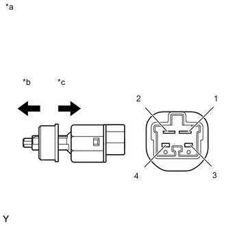
Text In Illustration *a Component without harness connected
(Stop Light Switch)
*b Released *c Pushed in Disconnect the A38 stop light switch connector.
-
Measure the resistance according to the value(s) in the table below.
Standard Resistance Tester Connection Condition Specified Condition 1 - 2 Stop light switch pin released Below 1 Ω Stop light switch pin pushed in 10 kΩ or higher 3 - 4 Stop light switch pin released 10 kΩ or higher Stop light switch pin pushed in Below 1 Ω
NG
REPLACE STOP LIGHT SWITCH Click here
OK
-
-
CHECK HARNESS AND CONNECTOR (BATTERY - STOP LIGHT SWITCH)
-
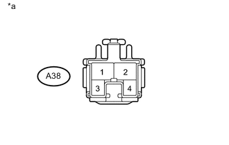
Text In Illustration *a Front view of wire harness connector
(to Stop Light Switch)
Measure the voltage according to the value(s) in the table below.
Standard Voltage Tester Connection Switch Condition Specified Condition A38-2 - Body ground Always 11 to 14 V A38-3 - Body ground Ignition switch ON 11 to 14 V
NG
REPAIR OR REPLACE HARNESS OR CONNECTOR
OK
-
-
CHECK HARNESS AND CONNECTOR (STOP LIGHT SWITCH - TCM)
-
Reconnect the A38 stop light switch connector.
-
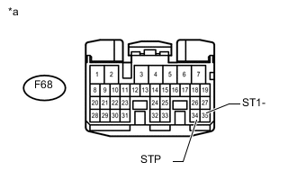
Text In Illustration *a Front view of wire harness connector
(to TCM)
Disconnect the F68 TCM connector.
-
Turn the ignition switch to ON.
-
Measure the voltage according to the value(s) in the table below.
Standard Voltage Tester Connection Condition Specified Condition F68-34 (STP) - Body ground Brake pedal is depressed 11 to 14 V Brake pedal is released Below 1 V F68-35 (ST1-) - Body ground Brake pedal is depressed Below 1 V Released 11 to 14 V
NG
REPAIR OR REPLACE HARNESS OR CONNECTOR
OK
-
-
REPLACE TCM
-
Replace the TCM Click here.
NEXT
-
-
PERFORM INITIALIZATION
-
Perform the initialization and learning for multi-mode manual transaxle system Click here.
NEXT
END
-