MULTI-MODE MANUAL TRANSAXLE SYSTEM, Diagnostic DTC:P0715
| DTC Code | DTC Name |
|---|---|
| P0715 | Input / Turbine Speed Sensor Circuit Malfunction |
DESCRIPTION
The transmission revolution sensor is mounted on the transaxle. The TCM calculates the transaxle input shaft speed using the sensor. When the input shaft rotates, the sensor generates a pulse signal and sends the signal to the TCM. The ECU calculates the input shaft speed based on the signal. If the input shaft speed falls below a threshold despite the vehicle running, the ECU interprets this as a malfunction in the transmission revolution sensor circuit. The ECU sets the DTC and illuminates the multi-mode manual transmission warning light.
| DTC No. | DTC Detection Condition | Trouble Area |
|---|---|---|
| P0715 | The TCM detects the following conditions simultaneously: (1-trip detection logic)
|
|
WIRING DIAGRAM
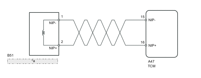
| *a | TRANSMISSION REVOLUTION SENSOR |
PROCEDURE
-
INSPECT SENSOR INSTALLATION (TRANSMISSION REVOLUTION SENSOR)
-
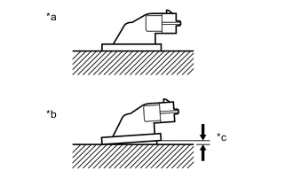
Text In Illustration *a Normal *b Abnormal *c Clearance Check the transmission revolution sensor installation.
OK Sensor is installed correctly.
NG 
SECURELY INSTALL OR REPLACE SENSOR
OK 
-
-
INSPECT TRANSMISSION REVOLUTION SENSOR
-
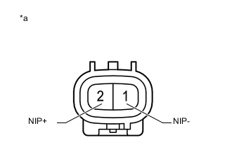
Text In Illustration *a Component without harness connected
(transmission revolution sensor)
Disconnect the B51 transmission revolution sensor connector.
-
Measure the resistance between the terminals of the transmission revolution sensor connector.
Standard Resistance Tester Connection Condition Specified Condition 1 (NIP-) - 2 (NIP+) 20°C (68°F) 560 to 680 Ω
NG
REPLACE TRANSMISSION REVOLUTION SENSOR Click here
OK
-
-
CHECK HARNESS AND CONNECTOR (TRANSMISSION REVOLUTION SENSOR - TCM)
-
Reconnect the B51 transmission revolution sensor connector.
-
Disconnect the A47 TCM connector.
-
Measure the resistance according to the value(s) in the table below.
Standard Resistance Tester Connection Condition Specified Condition A47-15 (NIP-) - A47-16 (NIP+) 20°C (68°F) 560 to 680 Ω A47-15 (NIP-) - Body ground Always 10 kΩ or higher A47-16 (NIP+) - Body ground Always 10 kΩ or higher
NG
REPAIR OR REPLACE HARNESS OR CONNECTOR
OK
-
-
REPLACE TCM
-
Replace the TCM Click here.
NEXT
-
-
PERFORM INITIALIZATION
-
Perform the initialization and learning for multi-mode manual transaxle system Click here.
NEXT
END
-