MANUAL TRANSAXLE ASSEMBLY INSTALLATION
CAUTION / NOTICE / HINT
Note
When the transaxle is removed, be sure to use a new clutch release with bearing cylinder and new installation bolts. Removal of the transaxle allows the compressed clutch release with bearing cylinder to return to its original position, and dust could damage the seal of the clutch release with bearing cylinder, possibly causing clutch fluid leaks.
PROCEDURE
-
INSTALL CLUTCH FLEXIBLE HOSE BRACKET
-
INSTALL CLUTCH RELEASE WITH BEARING CYLINDER ASSEMBLY
-
REMOVE CLUTCH RELEASE BLEEDER SUB-ASSEMBLY
-
INSPECT CLUTCH PIPE LINE
-
INSTALL CLUTCH RELEASE BLEEDER SUB-ASSEMBLY
-
INSTALL CLUTCH RELEASE CYLINDER TO FLEXIBLE HOSE TUBE
-
INSTALL WIRE HARNESS CLAMP BRACKET
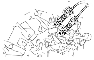
-
Install the wire harness clamp bracket with the bolt and nut.
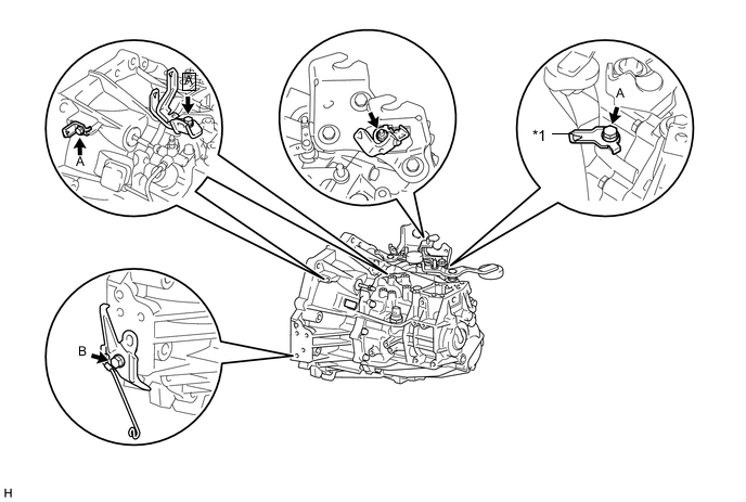
Text in Illustration *1 w/ Stop and Start System - - - Torque:
- Bolt A
- 13 N*m { 130 kgf*cm, 9 ft.*lbf }
- Bolt B
- 29 N*m { 296 kgf*cm, 21 ft.*lbf }
- Nut
- 8.4 N*m { 85 kgf*cm, 74 in.*lbf }
-
-
INSTALL MANUAL TRANSAXLE ASSEMBLY
-
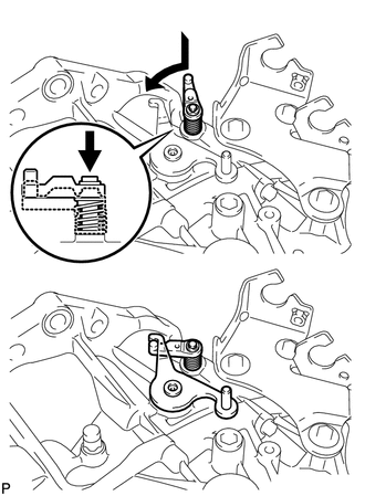
Hook the outer lever to the low fixture lever of the reverse restrict pin to secure it.
-
Make sure that the knock pins are not loose, bent, damaged or scratched and then install the transaxle onto the engine with the contact surfaces of the engine and transaxle flat against each other.
-
Align the input shaft with the clutch disc and install the manual transaxle assembly onto the engine.
-
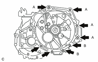
Install the 8 bolts.
- Torque:
- Part A
- 64 N*m { 653 kgf*cm, 47 ft.*lbf }
- Part B
- 39 N*m { 397 kgf*cm, 29 ft.*lbf }
Note
Insert knock pins into the knock pin holes securely so that the end face of the manual transaxle assembly fits close against the engine assembly before tightening the bolts.
-
-
INSTALL ENGINE MOUNTING BRACKET SUB-ASSEMBLY LH
-
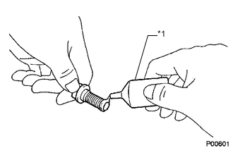
Text in Illustration *1 Toyota Genuine Adhesive 1324 Coat the threads of the bolts with sealant.
Sealant Toyota Genuine Adhesive 1324, Three Bond 1324 or equivalent -
Install the engine mounting bracket sub-assembly LH with the 4 bolts.
- Torque:
- 64 N*m { 653 kgf*cm, 47 ft.*lbf }
-
-
INSTALL ENGINE MOUNTING INSULATOR LH
-
Install the engine mounting insulator LH with the 5 bolts.
- Torque:
- 52 N*m { 530 kgf*cm, 38 ft.*lbf }
-
Install the engine mounting bracket sub-assembly LH and engine mounting insulator LH with the bolt and nut.
- Torque:
- 52 N*m { 530 kgf*cm, 38 ft.*lbf }
-
-
INSTALL ENGINE MOVING CONTROL ROD BRACKET
-
Install the engine moving control rod bracket with the 3 bolts.
- Torque:
- 45 N*m { 459 kgf*cm, 33 ft.*lbf }
-
-
INSTALL FRONT SUSPENSION CROSSMEMBER SUB-ASSEMBLY
-
INSTALL FRONT DRIVE SHAFT ASSEMBLES
-
INSTALL STARTER ASSEMBLY (w/ Stop and Start System)
-
INSTALL FLYWHEEL HOUSING SIDE COVER (w/ Stop and Start System)
-
INSTALL STARTER ASSEMBLY (w/o Stop and Start System)
-
INSTALL FLYWHEEL HOUSING SIDE COVER (w/o Stop and Start System)
-
CONNECT TRANSMISSION CONTROL CABLE ASSEMBLY
-
Connect the 2 cable ends and install the 2 washers and the 2 clips.
-
Install 2 new clips onto the control cable bracket.
-
-
INSTALL CLUTCH HOSE
-
Install the clutch hose into the flexible hose bracket with a new clip.
-
Using a union nut wrench (10 mm), install the flexible hose tube into the clutch hose.
- Torque:
- 15 N*m { 155 kgf*cm, 11 ft.*lbf }
Note
This torque value can be obtained by using a torque wrench with a fulcrum length of 250 mm (9.84 in.) and a union nut wrench with a fulcrum length of 22 mm (0.866 in.) Click here
-
-
CONNECT CONNECTOR (w/ Stop and Start System)
-
Attach the 2 clamps and connect the park/neutral position switch connector.
-
-
CONNECT WIRE HARNESS
-
Attach the 6 clamps and connect the 2 connectors.
-
Connect the wire harness with the bolt.
- Torque:
- 13 N*m { 130 kgf*cm, 9 ft.*lbf }
-
-
CONNECT WATER HOSE SUB-ASSEMBLY
-
Attach the 2 hose clamp to the wire harness clamp brackets.
-
-
INSTALL BATTERY CARRIER
-
INSTALL BATTERY TRAY
-
INSTALL BATTERY
-
ADD TRANSAXLE OIL
-
INSPECT TRANSAXLE OIL
-
INSTALL ENGINE UNDER COVER RH
-
INSTALL ENGINE UNDER COVER LH
-
REMOVE NO. 1 STEERING COLUMN HOLE COVER SUB-ASSEMBLY
-
INSTALL STEERING SLIDING YOKE SUB-ASSEMBLY
-
INSTALL COLUMN HOLE COVER SILENCER SHEET
-
CONNECT CABLE TO NEGATIVE BATTERY TERMINAL
- Torque:
- 5.4 N*m { 55 kgf*cm, 48 in.*lbf }
-
INSPECT ABS SPEED SENSOR SIGNAL (w/o VSC)
-
INSPECT ABS SPEED SENSOR SIGNAL (w/ VSC)
-
INSPECT AND ADJUST FRONT WHEEL ALIGNMENT
-
INSPECT FOR EXHAUST GAS LEAK
-
INSPECT FOR TRANSAXLE OIL LEAK