MANUAL TRANSAXLE ASSEMBLY REMOVAL
CAUTION / NOTICE / HINT
Note
When the transaxle is removed, be sure to use a new clutch release with bearing cylinder and new installation bolts. Removal of the transaxle allows the compressed clutch release with bearing cylinder to return to its original position, and dust could damage the seal of the clutch release with bearing cylinder, possibly causing clutch fluid leaks.
PROCEDURE
-
DISCONNECT CABLE FROM NEGATIVE BATTERY TERMINAL
-
REMOVE BATTERY
-
REMOVE BATTERY TRAY
-
REMOVE BATTERY CARRIER
-
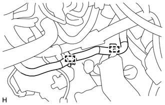
DISCONNECT WATER HOSE SUB-ASSEMBLY
-
Detach the 2 hose clamps and disconnect the water hose sub-assembly.
-
-
DISCONNECT WIRE HARNESS
-
Remove the bolt, then disconnect the wire harness.
-
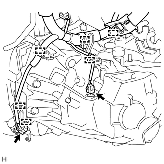
Detach the 6 clamps and disconnect the 2 connectors.
-
-
DISCONNECT CONNECTOR (w/ Stop and Start System)
-
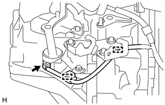
Detach the 2 clamps and disconnect the park/neutral position switch connector.
-
-
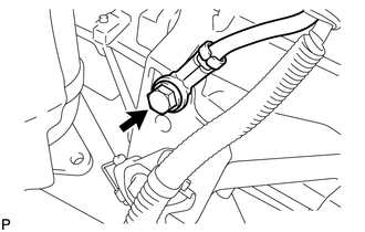
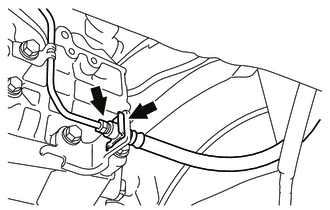
SEPARATE CLUTCH HOSE
-
Using a union nut wrench, separate the flexible hose tube from the clutch hose.
-
Remove the clip and separate the clutch hose from the flexible hose bracket.
-
-
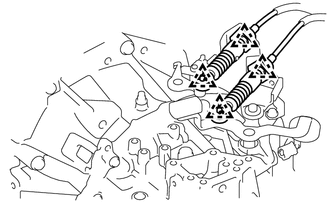
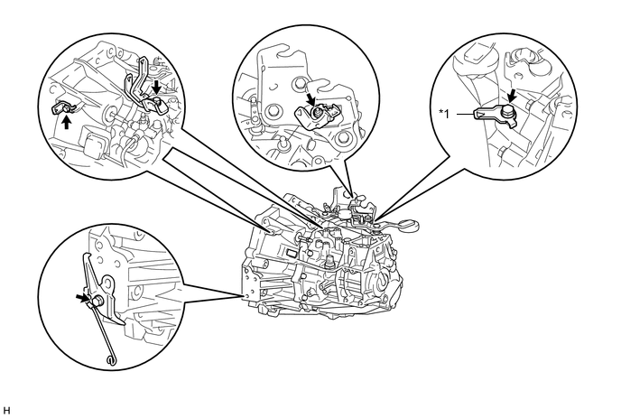
SEPARATE TRANSMISSION CONTROL CABLE ASSEMBLY
-
Remove the 4 clips and disconnect the 2 transmission control cables.
-
-
REMOVE COLUMN HOLE COVER SILENCER SHEET
-
REMOVE STEERING SLIDING YOKE SUB-ASSEMBLY
-
SEPARATE NO. 1 STEERING COLUMN HOLE COVER SUB-ASSEMBLY
-
REMOVE ENGINE UNDER COVER LH
-
REMOVE ENGINE UNDER COVER RH
-
DRAIN TRANSAXLE OIL
-
REMOVE FLYWHEEL HOUSING SIDE COVER (w/ Stop and Start System)
-
REMOVE STARTER ASSEMBLY (w/ Stop and Start System)
-
REMOVE FLYWHEEL HOUSING SIDE COVER (w/o Stop and Start System)
-
REMOVE STARTER ASSEMBLY (w/o Stop and Start System)
-
REMOVE FRONT DRIVE SHAFT ASSEMBLES
-
SUSPEND ENGINE ASSEMBLY
-
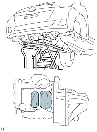
Support the engine assembly with an engine lifter so that it is stable shown in the illustration.
Text in Illustration 
Attachment Placement Positions
-
-
REMOVE FRONT SUSPENSION CROSSMEMBER SUB-ASSEMBLY
-
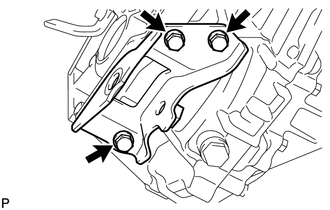
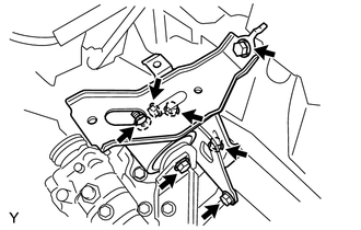
REMOVE ENGINE MOVING CONTROL ROD BRACKET
-
Remove the 3 bolts and the engine moving control rod bracket.
-
-
SUPPORT MANUAL TRANSAXLE ASSEMBLY
-
Support the manual transaxle assembly with a transmission jack so that it is stable.
-
-
REMOVE ENGINE MOUNTING INSULATOR LH
-
Remove the bolt and nut, then separate the engine mounting insulator LH.
-
Remove the 5 bolts and the engine mounting insulator LH.
-
-
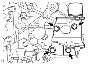
REMOVE ENGINE MOUNTING BRACKET SUB-ASSEMBLY LH
-
Remove the 4 bolts and the engine mounting bracket sub-assembly LH.
-
-
REMOVE MANUAL TRANSAXLE ASSEMBLY
-
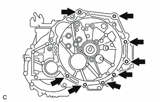
Remove the 8 bolts and the manual transaxle assembly.
-
-
REMOVE WIRE HARNESS CLAMP BRACKET
Text in Illustration *1 Wire Harness Bracket (w/ Stop and Start System) - -
-
Remove the bolts and nut and wire harness clamp brackets as shown in the illustration.
-
-
REMOVE CLUTCH RELEASE CYLINDER TO FLEXIBLE HOSE TUBE
-
REMOVE CLUTCH RELEASE BLEEDER SUB-ASSEMBLY
-
REMOVE CLUTCH TUBE BOOT
-
REMOVE CLUTCH RELEASE WITH BEARING CYLINDER ASSEMBLY
-
REMOVE BLEEDER CLUTCH RELEASE TUBE
-
REMOVE CLUTCH FLEXIBLE HOSE BRACKET