DIFFERENTIAL CASE INSPECTION

PROCEDURE
-
INSPECT FRONT DIFFERENTIAL CASE
-
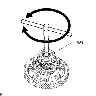
Install SST as shown in the illustration, and then rotate the front differential side gear as shown in the illustration.
- SST
- 09528-52010 ( 09528-05040 )
Standard The gear does not lock when rotated in either direction.
-
If the front differential side gear locks, perform all remaining inspection procedures.
-
Replace any parts that do not meet the specifications.
-
If the front differential side gear locks after performing the inspection procedures again, replace the front No. 1 differential case assembly.
-
-
INSPECT FRONT DIFFERENTIAL SIDE GEAR THRUST AMOUNT
-
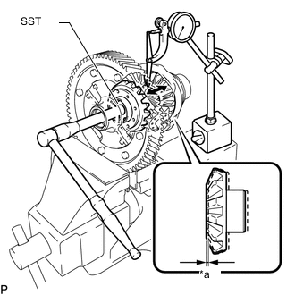
Text in Illustration *a Front differential side gear thrust amount Using SST and dial indicator, measure the thrust amount of the front differential side gear.
- SST
- 09528-52010 ( 09528-05040 )
Front differential side gear thrust amount 0.08 mm (0.00314 in.) or less Tech Tips
-
Measure the front differential side gear thrust amount while slowly rotating the front differential side gear.
-
Make sure to measure the thrust amount for both of the 2 front differential side gears.
If the result is not as specified, replace the 2 conical springs, 2 front differential side gears and 2 front differential pinions.
-
-
INSPECT FRONT DIFFERENTIAL PINION BACKLASH
-
Set SST as shown in the illustration and tighten it.
- SST
- 09528-52010 ( 09953-05010, 09528-05020 )
- Torque:
- 10 N*m { 102 kgf*cm, 8 ft.*lbf }
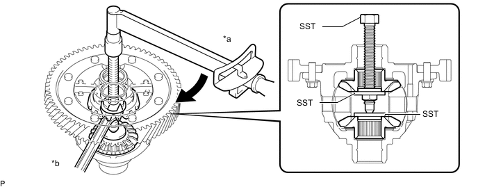
Text in Illustration *a Turn *b Hold -
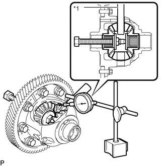
Text in Illustration *1 Front No. 1 Differential Pinion Shaft Install the front No. 1 differential pinion shaft to the pinion gear as shown in the illustration.
-
Using a dial indicator, measure the front differential pinion backlash.
Standard backlash 0.05 to 0.20 mm (0.00197 to 0.00787 in.) Tech Tips
Make sure to measure the front differential pinion backlash for both of the 2 front differential pinions.
If the backlash is not as specified, replace the front No. 1 differential side gear thrust washers with washers of a different thickness. Use the table below to select a front No. 1 differential side gear thrust washer which will ensure that the backlash is within the specification.
Thrust Washer Thickness Mark Specified Condition 14 0.95 mm (0.0374 in.) 02 1.00 mm (0.0394 in.) 15 1.05 mm (0.0413 in.) 03 1.10 mm (0.0433 in.) 16 1.15 mm (0.0452 in.) 04 1.20 mm (0.0472 in.) Tech Tips
Select washers of the same thickness for both the right and left sides.
-
-
INSPECT FRONT DIFFERENTIAL PINION THRUST WASHER
-
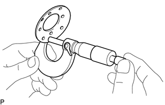
Using a micrometer, measure the thickness of the front differential pinion thrust washer.
Standard thickness 0.92 to 1.08 mm (0.0363 to 0.0425 in.) Minimum thickness 0.92 mm (0.0363 in.) If the thickness is less than the minimum, replace the front differential pinion thrust washer.
-
-
INSPECT FRONT NO. 1 DIFFERENTIAL PINION SHAFT
-
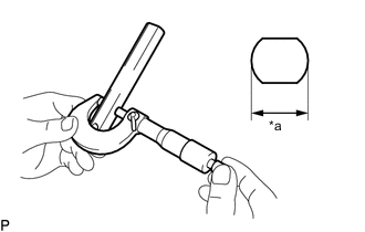
Text in Illustration *a Minimum Outer Diameter Using a micrometer, measure the outer diameter of the front No. 1 differential pinion shaft.
Standard outer diameter 16.982 to 17.000 mm (0.6686 to 0.6692 in.) Minimum outer diameter 16.982 mm (0.6686 in.) If the outer diameter is less than the minimum, replace the front No. 1 differential pinion shaft.
-