CLUTCH ACTUATOR(for EC65A) INSTALLATION
PROCEDURE
-
INSTALL NO. 1 CLUTCH ACTUATOR BRACKET
-
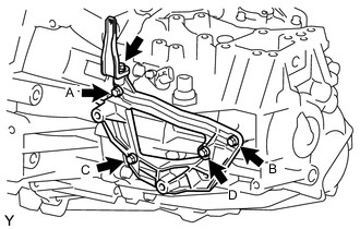
Temporarily tighten the bolt B.
-
Tighten the bolt A.
- Torque:
- 17 N*m { 173 kgf*cm, 13 ft.*lbf }
-
Tighten the bolt B, C and D.
- Torque:
- 17 N*m { 173 kgf*cm, 13 ft.*lbf }
-
Install the wire harness clamp bracket with the bolt onto the No. 1 clutch actuator assembly.
- Torque:
- 13 N*m { 130 kgf*cm, 9 ft.*lbf }
-
-
INSTALL CLUTCH ACTUATOR ASSEMBLY
-
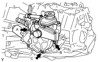
Temporarily tighten the bolt B.
-
Tighten the bolt A.
- Torque:
- 17 N*m { 173 kgf*cm, 13 ft.*lbf }
-
Tighten the bolt B and C.
- Torque:
- 17 N*m { 173 kgf*cm, 13 ft.*lbf }
-
-
INSTALL BLEEDER CLUTCH RELEASE TUBE
-
Using a union nut wrench 10 mm, install the bleeder clutch release tube.
- Torque:
- 15 N*m { 155 kgf*cm, 11 ft.*lbf }
Note
Use the formula to calculate special torque values for situations where union nut wrench is combined with a torque wrench Click here.
-
-
INSTALL WIRE HARNESS CLAMP BRACKET
-
Connect the connector onto the clutch actuator and engage the wire harness clamp onto the wire harness clamp bracket.
-
Install the wire harness clamp bracket with the bolt.
- Torque:
- 13 N*m { 130 kgf*cm, 9 ft.*lbf }
-
-
INSTALL AIR CLEANER BRACKET
-
BLEED CLUTCH LINE
-
PERFORM INITIALIZATION OF MULTI-MODE MANUAL TRANSMISSION ECU
-
PERFORM LEARNING OF MULTI-MODE TRANSMISSION SYSTEM
-
PERFORM SYNCHRONIZATION POSITION CALIBRATION
-
INSTALL AIR CLEANER CASE SUB-ASSEMBLY
-
INSTALL AIR CLEANER FILTER ELEMENT SUB-ASSEMBLY
-
INSTALL AIR CLEANER CAP SUB-ASSEMBLY