STOP AND START SYSTEM TERMINALS OF ECU
-
ENGINE STOP AND START ECU
-
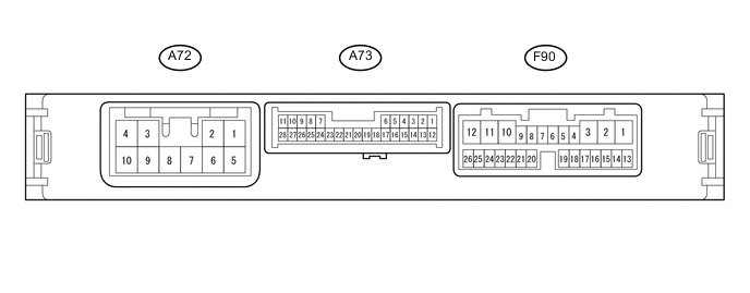
Disconnect the A72, A73 and F90 engine stop and start ECU connectors.
-
Measure the resistance and voltage according to the value(s) in the table below.
Terminal No.
(Symbol)
Wiring Color Terminal Description Condition Specified Condition A72-5 (+B) - Body ground B - Body ground Power source of engine stop and start ECU Ignition switch ON 9.5 to 14 V A72-7 (BIN) - Body ground B - Body ground Battery Always 9.5 to 14 V A72-8 (GND) - Body ground W-B - Body ground Ground Always Below 1 Ω A73-10 (NE) - Body ground V - Body ground Engine speed signal from ECM Always 10 kΩ or higher A73-17 (VB-) - Body ground W-B - Body ground Ground Always Below 1 Ω F90-15 (CANH) - Body ground P - Body ground CAN communication Always 10 kΩ or higher F90-16 (CANL) - Body ground W - Body ground CAN communication Always 10 kΩ or higher F90-17 (IG1) - Body ground LG - Body ground Ignition switch signal Ignition switch ON 9.5 to 14 V F90-19 (ACC) - Body ground R - Body ground Ignition switch signal Ignition switch ACC 9.5 to 14 V F90-20 (IG2) - Body ground B - Body ground Ignition switch signal Ignition switch ON 9.5 to 14 V -
Reconnect the A72, A73 and F90 engine stop and start ECU connectors.
-
Measure the resistance and voltage according to the value(s) in the table below.
Terminal No.
(Symbol)
Wiring Color Terminal Description Condition Specified Condition A72-6 (OPO) - A73-8 (GND) B - Body ground Oil pump with motor assembly (oil pump motor) power source signal When the engine is stopped by stop and start control system, or when performing the AT Oil Pump Lo Drive of the Active Test. 10 to 14 V A73-3 (BRE2) - Body ground R - Body ground Ground (vacuum sensor assembly (brake booster pressure sensor)) Always Below 1 Ω A73-7 (BNT1) - A8-8 (GND) P - W-B Engine hood courtesy switch (hood lock assembly) signal
-
Ignition switch ON
-
Engine stopped
-
Engine hood closed
0 to 1.5 V
-
Ignition switch ON
-
Engine stopped
-
Engine hood open
8 to 14 V A72-9 (OPM1) - A73-8 (GND) B - Body ground Oil pump with motor assembly (oil pump motor) power source signal When the engine is stopped by stop and start control system, or when performing the AT Oil Pump Lo Drive of the Active Test. Pulse generation
(see waveform 1)
A73-10 (NE) - A72-8 (GND) V - W-B Engine speed signal from ECM Idling after engine warmed up Pulse generation
(see waveform 2)
A73-13 (PB) - A73-3 (BRE2) LG - R Vacuum sensor assembly (brake booster pressure sensor) signal
-
Ignition switch ON
-
Absolute pressure of 40 kPa (0.4 kgf/cm2, 5.8 psi) applied to vacuum sensor assembly (brake booster pressure sensor)
1.6 to 2.0 V
-
Ignition switch ON
-
Absolute pressure of 60 kPa (0.6 kgf/cm2, 8.7 psi) applied to vacuum sensor assembly (brake booster pressure sensor)
2.2 to 2.6 V
-
Ignition switch ON
-
Atmospheric pressure applied to vacuum sensor assembly (brake booster pressure sensor)
3.4 to 3.8 V A73-14 (BRVC) - A72-8 (GND) G - W-B Vacuum sensor assembly (brake booster pressure sensor) power supply
-
Ignition switch ON
-
Engine stopped
4.5 to 5.5 V A73-21 (STA) - A72-8 (GND) G - W-B Starter pinion activation signal Cranking 6.0 V or more A73-23 (STA2) - A73-8 (GND) B - Body ground Starter motor activation signal Cranking 6.0 V or more A73-27 (NOPM) - A73-8 (GND) B - Body ground Oil pump with motor assembly (oil pump motor) power source signal Idling after engine warmed up 10 to 14 V When the engine is stopped by stop and start control system, or when performing the AT Oil Pump Lo Drive of the Active Test. Pulse generation
(see waveform 3)
A73-28 (CLL) - A72-8 (GND) L - W-B Park/neutral switch assembly signal
-
Ignition switch ON
-
Shift lever in any other than N or P
8 to 14 V
-
Ignition switch ON
-
Shift lever in N or P
Below 3.0 V F90-2 (BO1) - A72-8 (GND) SB - W-B Backup boost converter signal Always 9.5 to 14 V F90-3 (ACO) - A72-8 (GND) GR - W-B Backup boost converter signal Ignition switch ACC 9.5 to 14 V F90-11 (IG02) - A72-8 (GND) P - W-B Backup boost converter signal Ignition switch ON 9.5 to 14 V F90-12 (IG01) - A72-8 (GND) B - W-B Backup boost converter signal Ignition switch ON 9.5 to 14 V F90-17 (IG1) - A72-8 (GND) LG - W-B Ignition switch signal Ignition switch ACC Below 1 V Ignition switch ON 9.5 to 14 V F90-19 (ACC) - A72-8 (GND) R - W-B Ignition switch signal Ignition switch off Below 1 V Ignition switch ACC 9.5 to 14 V F90-20 (IG2) - A72-8 (GND) B - W-B Ignition switch signal Ignition switch ACC Below 1 V Ignition switch ON 9.5 to 14 V F90-23 (ECAN) - A72-8 (GND) SB - W-B Stop and start system cancel switch (Stop and start cancel switch assembly) signal
-
Ignition switch ON
-
Stop and start system cancel switch (Stop and start cancel switch assembly) pressed
0 to 1.5 V
-
Ignition switch ON
-
Stop and start system cancel switch (Stop and start cancel switch assembly) not pressed
8 to 14 V -
-
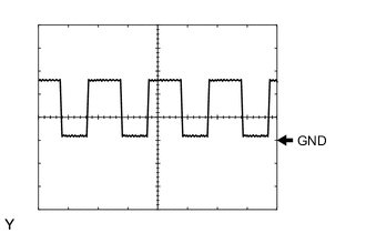
Waveform 1
Engine Speed Signal Item Content Tester connection OPM1 - GND Tool setting 5 V/DIV, 5 ms/DIV Condition When the engine is stopped by stop and start control system, or when performing the AT Oil Pump Lo Drive of the Active Test. -
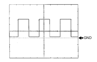
Waveform 2
Engine Speed Signal Item Content Tester connection NE - GND Tool setting 5 V/DIV, 2 ms/DIV Condition Idling after engine warmed up Tech Tips
The wavelength become shorter as the engine speed increases.
-
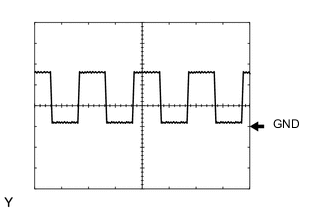
Waveform 3
Engine Speed Signal Item Content Tester connection NOPM - GND Tool setting 5 V/DIV, 5 ms/DIV Condition When the engine is stopped by stop and start control system, or when performing the AT Oil Pump Lo Drive of the Active Test.
-