STOP AND START SYSTEM Starter Inrush Current Reduction Relay Circuit
DESCRIPTION
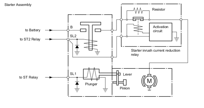
The starter inrush current reduction relay reduces the drop in battery voltage when the starter is operated.
When battery voltage drops below the minimum threshold, stop and start control is prohibited. To avoid this, the stop and start ECU activates the start inrush current reduction relay approximately 0.1 seconds after ST/ST2 relay turns on, so that current flows through the resistor, lowering the current flowing to the starter motor and reducing the drop in battery voltage.
WIRING DIAGRAM
Refer to P0617 Click here.
PROCEDURE
-
INSPECT BATTERY
-
Connect the GTS to the DLC3.
-
Turn the ignition switch to ON.
-
Turn the GTS on.
-
Enter the following menus: Powertrain / Stop and Start / Active Test / Starter Motor Drive Magnet Switch / Min Volt (After Cranking)
-
Connect the oscilloscope positive probe to the positive (+) terminal on the battery, and the negative probe to the negative (-) terminal on the battery.
-
Read the number of drops in the waveform when the starter motor is forced to operate in the Active Test and the minimum voltage value after cranking in the Data Monitor.
Note
-
Starter motor operation during the Active Test stops automatically in 3 seconds.
-
Do not force the starter pinion to operate.
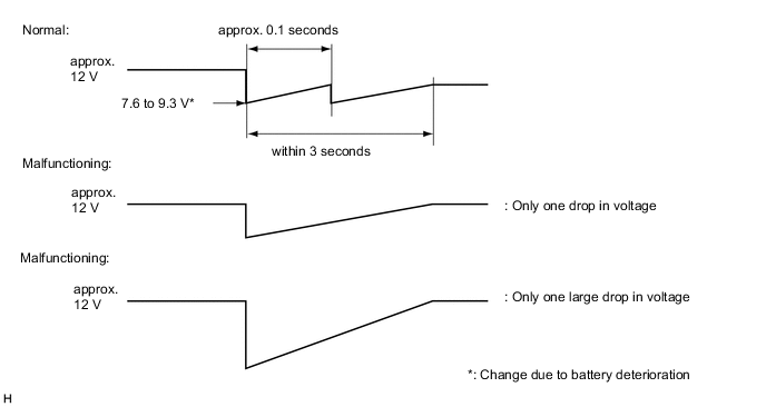
OK There are 2 peaks in the voltage waveform, and minimum voltage after cranking is approximately 7.6 V or more Result [Number of drops in waveform] Result Minimum voltage after cranking (Data Monitor item) Proceed to There are 2 drops. 7.6 V or more A There are 2 drops. 7.6 V or less B There are not 2 drops. 7.6 V or more C There are not 2 drops. 7.6 V or less D -
B 
INSPECT BATTERY Click here
C
REPLACE STARTER INRUSH CURRENT REDUCTION RELAY Click here
D
REPLACE STARTER INRUSH CURRENT REDUCTION RELAY AND INSPECT BATTERY
A 
-
-
INSPECT ENGINE STOP AND START ECU
-
Connect the GTS to the DLC3.
-
Turn the ignition switch to ON.
-
Turn the GTS on.
-
Enter the following menus: Powertrain / Stop and Start / Active Test / Starter Motor Drive Magnet Switch
-
Connect the oscilloscope positive probe to the positive (+) terminal on the battery and the A73-21 (STA) terminal on the engine stop and start ECU, and then connect the negative probe to the negative (-) terminal on the battery and the A72-8 (GND) terminal on the engine stop and start ECU.
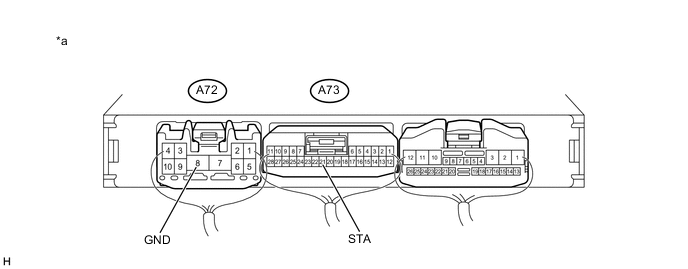
Text In Illustration *a Component with harness connected:
(Engine Stop and Start ECU)
- - -
Read the battery voltage when the starter motor is forced to operate in the Active Test
Note
Starter operation in the Active Test stops automatically in 3 seconds.
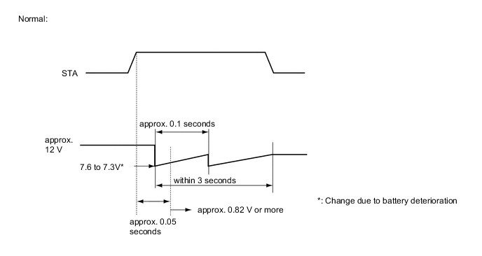
OK The minimum voltage immediately after cranking is at least 7.6 V, and approximately 8.2 V or more approximately 0.05 seconds after the ST relay is turned on. Tech Tips
Check the following items at the same time using the GTS.
-
Powertrain / Stop and Start / Data List / Min Volt (After Cranking) : 7.6 V or more
-
Powertrain / Stop and Start / Data List / Min Voltage (Cranking) : 7.6 V or more
-
OK
USE SIMULATION METHOD TO CHECK Click here
NG
INSPECT BATTERY Click here
-