STOP AND START SYSTEM Starter Signal Circuit
DESCRIPTION
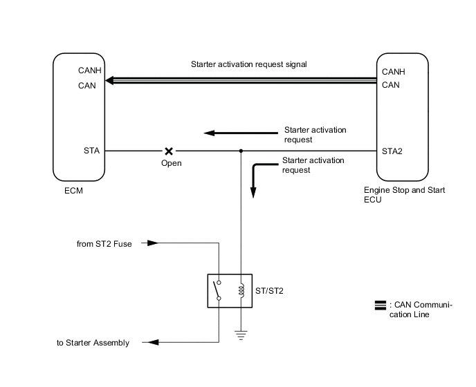
When the engine is being cranked, a starter activation request is also sent to the ECM STA terminal.
Tech Tips
When the ECM STA circuit is open, after the engine starts, stop and start control is not permitted to operate more than 4 times.
-
Stop and start prohibition only occurs for trips where a malfunction has been detected
-
MIL does not light
-
The engine can be started with the ignition or starter switch assembly or the push start switch (stop and start control is prohibited by the reliability of CAN transmission for voltage drops due to starter activation.)
WIRING DIAGRAM
Refer to P0617 Click here.
PROCEDURE
-
READ VALUE USING GTS (ENGINE STARTER SIGNAL)
-
Connect the GTS to the DLC3.
-
Turn the ignition switch to ON.
-
Turn the GTS on.
-
Enter the following menus: Powertrain / Stop and Start / Data List / Engine Starter Signal.
-
Check the Data Monitor when the ignition or starter switch assembly or the push start switch is operated.
OK Ignition switch Engine Starter Signal ON OFF START ON
OK 
USE SIMULATION METHOD TO CHECK Click here
NG 
-
-
CHECK HARNESS AND CONNECTOR (ENGINE STOP AND START ECU - ST2 RELAY)
-
Disconnect the A58 ECM connector.
-
Remove the ST2 relay from engine room relay block.
-
Measure the resistance according to the value(s) in the table below.
Standard Resistance Tester Connection Condition Specified Condition A58-22 (STA) - ST2 relay holder 2 Always Below 1 Ω
OK
USE SIMULATION METHOD TO CHECK Click here
NG
REPAIR OR REPLACE HARNESS OR CONNECTOR Click here
-