STOP AND START SYSTEM Park / Neutral Position Switch Circuit
DESCRIPTION
The engine stop and start ECU detects the neutral position through the park/neutral position switch assembly attached to the transaxle.
WIRING DIAGRAM
Refer to P1780 Click here.
CAUTION / NOTICE / HINT
Note
Inspect the fuses for circuits related to this system before performing the following inspection procedure.
PROCEDURE
-
READ VALUE USING INTELLIGENT TESTER (NEUTRAL POSITION SWITCH)
-
Connect the intelligent tester to the DLC3.
-
Turn the ignition switch to ON.
-
Turn the tester on.
-
Enter the following menus: Powertrain / ECT / Data List.
-
In accordance with the display on the tester, read the Data List.
Tester Display Measurement Item / Range Normal Condition Diagnostic Note Neutral Position SW Signal PNP switch status /
ON or OFF
ON: Shift lever in P or N
OFF: Shift lever not in P or N
- Result Result Proceed to Data display is not within Normal Condition range A Data display is within Normal Condition range B
B 
PROCEED TO NEXT SUSPECTED AREA SHOWN IN PROBLEM SYMPTOMS TABLE Click here
A 
-
-
INSPECT PARK/NEUTRAL POSITION SWITCH ASSEMBLY
-
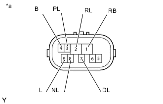
Text In Illustration *a Component without harness connected
(Park/Neutral Position Switch Assembly)
Disconnect the B69 park/neutral position switch connector.
-
Measure the resistance according to the value(s) in the table below.
Standard Resistance Tester Connection Condition Specified Condition
-
1 (RB) - 3 (PL)
-
4 (B) - 9 (L)
Shift lever in P Below 1 Ω 1 (RB) - 2 (RL) Shift lever in R Below 1 Ω
-
1 (RB) - 8 (NL)
-
4 (B) - 9 (L)
Shift lever in N Below 1 Ω 1 (RB) - 7 (DL) Shift lever in D or M Below 1 Ω
-
1 (RB) - 3 (PL)
-
4 (B) - 9 (L)
Shift lever not in P 10 kΩ or higher 1 (RB) - 2 (RL) Shift lever not in R 10 kΩ or higher
-
1 (RB) - 8 (NL)
-
4 (B) - 9 (L)
Shift lever not in N 10 kΩ or higher 1 (RB) - 7 (DL) Shift lever not in D or M 10 kΩ or higher -
NG
REPLACE PARK/NEUTRAL POSITION SWITCH ASSEMBLY Click here
OK
-
-
CHECK HARNESS AND CONNECTOR (ENGINE STOP AND START ECU - PARK/NEUTRAL POSITION SWITCH)
-
Disconnect the A53 engine stop and start ECU connector.
-
Disconnect the B69 park/neutral position switch connector.
-
Measure the resistance according to the value(s) in the table below.
Standard Resistance Tester Connection Condition Specified Condition A53-4 (STA) - B69-9 (L) Always Below 1 Ω A53-6 (CLL) - B69-4 (B) Always Below 1 Ω A53-4 (STA) - Body ground Always 80 to 180 Ω A53-6 (CLL) - Body ground Always 10 kΩ or higher B69-9 (L) - Body ground Always 80 to 180 Ω B69-4 (B) - Body ground Always 10 kΩ or higher -
Reconnect the A53 engine stop and start ECU connector.
-
Reconnect the B69 park/neutral position switch connector.
OK
REPLACE ENGINE STOP AND START ECU Click here
NG
REPAIR OR REPLACE HARNESS OR CONNECTOR
-