STOP AND START SYSTEM, Diagnostic DTC:P1540
| DTC Code | DTC Name |
|---|---|
| P1540 | Brake Booster Sensor Circuit (Open or Short) |
DESCRIPTION
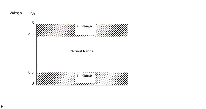
This description and the following Inspection Procedure are for DTC P1540 which is stored in the engine stop and start ECU. The vacuum sensor assembly detects the brake booster pressure and represents it as a voltage value. The vacuum sensor assembly detects the absolute pressure inside the brake booster.
If an open or short in the circuit is detected based on the output voltage of the vacuum sensor assembly, this DTC will be stored.
| DTC No. | DTC Detection Condition | Trouble Area |
|---|---|---|
| P1540 | The following condition continues for 2 seconds or more (1 trip detection logic):
|
|
Tech Tips
DTCs for the Stop and Start system are not cleared even if the malfunction has been repaired. After repairing the malfunction, be sure to clear the DTCs Click here.
-
After troubleshooting, perform the following steps to recheck for DTCs.
Tech Tips
-
If the battery terminal has been disconnected, the stop and start will be prohibited. In this case, drive the vehicle for 15 to 40 minutes to permit the stop and start operation.
-
Allow the engine to idle for 3 minutes after the engine warms up and check that the engine speed is within 50 rpm of the target idle speed.
-
Connect the intelligent tester to the DLC3.
-
Clear the DTCs Click here.
-
Start the engine and allow it to idle for 15 seconds or more.
-
Stop the engine and turn the ignition switch to ON.
-
Enter the following menus: Powertrain / Stop and Start / Data List / Brake Boost Pressure.
-
While depressing the brake pedal several times, check that the Brake Boost Pressure value changes.
-
Check that no DTCs are output Click here.
-
-
Check if the Stop and Start system operates normally.
Tech Tips
-
If the battery terminal has been disconnected, the stop and start will be prohibited. In this case, drive the vehicle for 15 to 40 minutes to permit the stop and start operation.
-
Allow the engine to idle for 3 minutes after the engine warms up and check that the engine speed is within 50 rpm of the target idle speed.
-
for Manual transaxle
-
Warm up the engine.
-
Turn the air conditioning system off.
-
Drive the vehicle at 7 km/h (4.3 mph) or more.
-
Stop the vehicle. Move the shift lever to neutral and release the clutch pedal.
-
Check that the engine stops.
-
Depress the clutch pedal and check that the engine restarts.
-
-
for CVT
-
Warm up the engine.
-
Turn the air conditioning system off.
-
Drive the vehicle at 7 km/h (4.3 mph) or more.
-
Stop the vehicle with the shift lever in D and depressed the brake pedal.
-
Check that the engine stops.
-
Release the brake pedal and check that the engine restarts.
-
-
WIRING DIAGRAM
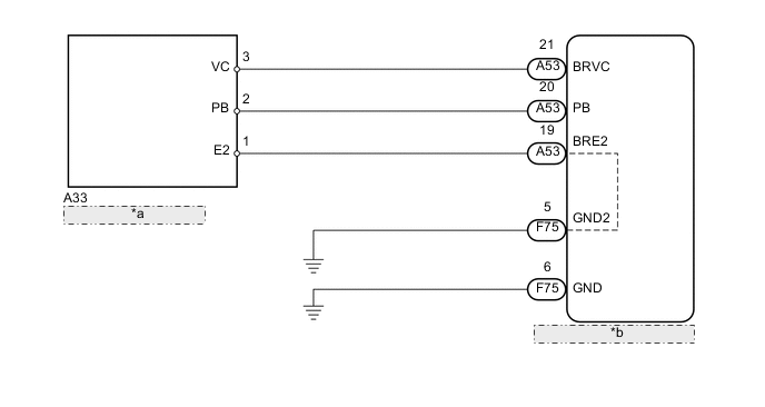
| *a | VACUUM SENSOR ASSEMBLY |
| *b | ENGINE STOP AND START ECU |
CAUTION / NOTICE / HINT
Note
-
If the engine stop and start ECU is being replaced, register the previously recorded number of starter operations into the new engine stop and start ECU Click here.
-
After the engine stop and start ECU is replaced or after an air conditioner kit is installed, clear the A/C information stored in the engine stop and start ECU Click here.
-
After the engine stop and start ECU or airbag sensor assembly (yaw rate sensor) is replaced, initialize and calibrate 0 point of deceleration sensor Click here.
PROCEDURE
-
INSPECT VACUUM SENSOR ASSEMBLY
-
Inspect the vacuum sensor assembly Click here.
NG 
REPLACE VACUUM SENSOR ASSEMBLY Click here
OK 
-
-
CHECK HARNESS AND CONNECTOR (ENGINE STOP AND START ECU - VACUUM SENSOR ASSEMBLY)
-
Disconnect the A53 engine stop and start ECU connector.
-
Disconnect the A33 vacuum sensor assembly connector.
-
Measure the resistance according to the value(s) in the table below.
Standard Resistance Tester Connection Condition Specified Condition A53-20 (PB) - A33-2 (PB) Always Below 1 Ω A53-21 (BRVC) - A33-3 (VC) Always Below 1 Ω A53-19 (BRE2) - A33-1 (E2) Always Below 1 Ω A53-20 (PB) or A33-2 (PB) - Body ground Always 10 kΩ or higher A53-21 (BRVC) or A33-3 (VC) - Body ground Always 10 kΩ or higher A53-19 (BRE2) or A33-1 (E2) - Body ground Always 10 kΩ or higher
OK
REPLACE ENGINE STOP AND START ECU Click here
NG
REPAIR OR REPLACE HARNESS OR CONNECTOR
-