STOP AND START SYSTEM, Diagnostic DTC:P1780
| DTC Code | DTC Name |
|---|---|
| P1780 | Park / Neutral Position Switch Malfunction |
DESCRIPTION
The engine stop and start ECU detects a malfunction by comparing the shift position signal with the park/neutral position switch input state. When a malfunction occurs, the engine stop and start ECU stores P1780, blinks the stop and start cancel indicator light, and stops the stop and start system control.
| DTC No. | Freeze Frame Data *1 | DTC Detection Condition | Trouble Area |
|---|---|---|---|
| P1780*2 | Neutral switch malfunction (stuck ON) | Either of the following conditions continues for 4 seconds or more (2 trip detection logic):
|
|
| Neutral switch malfunction (stuck OFF) | The following condition continues for 15 seconds or more (2 trip detection logic):
|
|
| DTC No. | DTC Detection Condition | Trouble Area |
|---|---|---|
| P1780*3 | The following condition continues for 1 second or more (1 trip detection logic):
|
|
-
*1: Since each information can be confirmed by freeze frame data, record the freeze frame data before deleting the diagnosis code.
-
*2: for CVT
-
*3: for Manual Transaxle
WIRING DIAGRAM
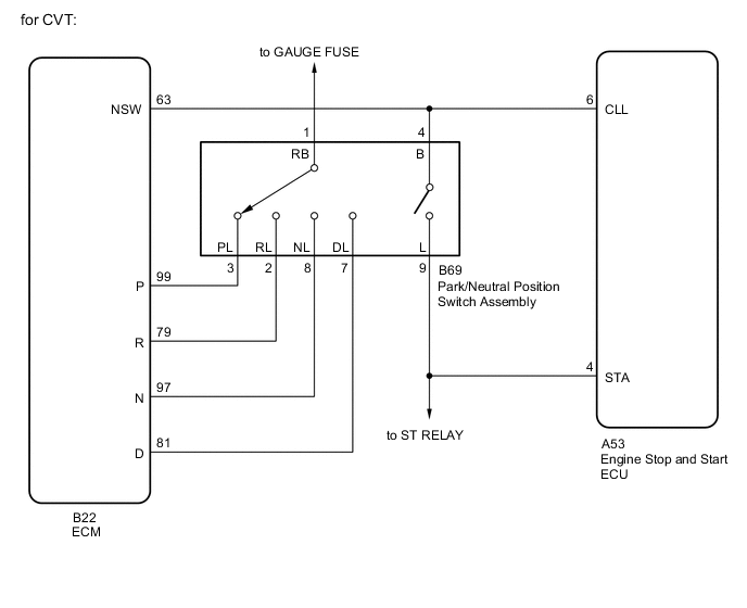
| *a | Neutral Position Switch |
| *b | Engine Stop and Start ECU |
CAUTION / NOTICE / HINT
Note
Inspect the fuses for circuits related to this system before performing the following inspection procedure.
PROCEDURE
-
CHECK SPECIFICATIONS
-
Check the vehicle specifications.
Result Result Proceed to CVT A Manual Transaxle B
B 
READ VALUE USING INTELLIGENT TESTER (NEUTRAL SWITCH) Click here
A 
-
-
READ VALUE USING INTELLIGENT TESTER (PARK/NEUTRAL POSITION SWITCH SIGNAL)
-
Connect the intelligent tester to the DLC3.
-
Turn the ignition switch to ON.
-
Turn the tester on.
-
Enter the following menus: Powertrain / Engine and ECT / Data List.
-
In accordance with the display on the tester, read the Data List.
Tester Display Measurement Item / Range Normal Condition Diagnostic Note Shift SW Status (P Range) PNP switch status /
ON or OFF
ON: Shift lever in P
OFF: Shift lever not in P
- Shift SW Status (R Range) PNP switch status /
ON or OFF
ON: Shift lever in R
OFF: Shift lever not in R
- Shift SW Status (N Range) PNP switch status /
ON or OFF
ON: Shift lever in N
OFF: Shift lever not in N
- Shift SW Status (D Range) PNP switch status /
ON or OFF
ON: Shift lever in D or M
OFF: Shift lever not in D or M
- Result Result Proceed to Data display is within Normal Condition range A Data display is not within Normal Condition range B
B
INSPECT PARK/NEUTRAL POSITION SWITCH ASSEMBLY Click here
A
-
-
READ VALUE USING INTELLIGENT TESTER (NEUTRAL POSITION SWITCH SIGNAL)
-
Connect the intelligent tester to the DLC3.
-
Turn the ignition switch to ON.
-
Turn the tester on.
-
Enter the following menus: Powertrain / Engine and ECT / Data List.
-
In accordance with the display on the tester, read the Data List.
Tester Display Measurement Item / Range Normal Condition Diagnostic Note Neutral Position SW Signal PNP switch status /
ON or OFF
ON: Shift lever in P or N
OFF: Shift lever not in P or N
- Result Result Proceed to Data display is not within Normal Condition range A Data display is within Normal Condition range B
B 
CHECK FOR INTERMITTENT PROBLEMS Click here
A
-
-
INSPECT PARK/NEUTRAL POSITION SWITCH ASSEMBLY
-
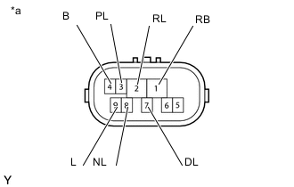
Text In Illustration *a Component without harness connected
(Park/Neutral Position Switch Assembly)
Disconnect the B69 park/neutral position switch connector.
-
Measure the resistance according to the value(s) in the table below.
Standard Resistance Tester Connection Condition Specified Condition
-
1 (RB) - 3 (PL)
-
4 (B) - 9 (L)
Shift lever in P Below 1 Ω 1 (RB) - 2 (RL) Shift lever in R Below 1 Ω
-
1 (RB) - 8 (NL)
-
4 (B) - 9 (L)
Shift lever in N Below 1 Ω 1 (RB) - 7 (DL) Shift lever in D or M Below 1 Ω
-
1 (RB) - 3 (PL)
-
4 (B) - 9 (L)
Shift lever not in P 10 kΩ or higher 1 (RB) - 2 (RL) Shift lever not in R 10 kΩ or higher
-
1 (RB) - 8 (NL)
-
4 (B) - 9 (L)
Shift lever not in N 10 kΩ or higher 1 (RB) - 7 (DL) Shift lever not in D or M 10 kΩ or higher -
NG
REPLACE PARK/NEUTRAL POSITION SWITCH ASSEMBLY Click here
OK
-
-
CHECK HARNESS AND CONNECTOR (ENGINE STOP AND START ECU - PARK/NEUTRAL POSITION SWITCH)
-
Disconnect the A53 engine stop and start ECU connector.
-
Measure the resistance according to the value(s) in the table below.
Standard Resistance Tester Connection Condition Specified Condition A53-4 (STA) - B69-9 (L) Always Below 1 Ω A53-6 (CLL) - B69-4 (B) Always Below 1 Ω A53-4 (STA) - Body ground Always 80 to 180Ω A53-6 (CLL) - Body ground Always 10 kΩ or higher B69-9 (L) - Body ground Always 80 to 180Ω B69-4 (B) - Body ground Always 10 kΩ or higher -
Reconnect the A53 engine stop and start ECU connector.
-
Reconnect the B69 park/neutral position switch connector.
OK
REPLACE ENGINE STOP AND START ECU Click here
NG
REPAIR OR REPLACE HARNESS OR CONNECTOR
-
-
INSPECT PARK/NEUTRAL POSITION SWITCH ASSEMBLY
-
Disconnect the B69 park/neutral position switch connector.
-
Text In Illustration *a Component without harness connected
(Park/Neutral Position Switch Assembly)
Measure the resistance according to the value(s) in the table below.
Standard Resistance Tester Connection Condition Specified Condition
-
1 (RB) - 3 (PL)
-
4 (B) - 9 (L)
Shift lever in P Below 1 Ω 1 (RB) - 2 (RL) Shift lever in R Below 1 Ω
-
1 (RB) - 8 (NL)
-
4 (B) - 9 (L)
Shift lever in N Below 1 Ω 1 (RB) - 7 (DL) Shift lever in D or M Below 1 Ω
-
1 (RB) - 3 (PL)
-
4 (B) - 9 (L)
Shift lever not in P 10 kΩ or higher 1 (RB) - 2 (RL) Shift lever not in R 10 kΩ or higher
-
1 (RB) - 8 (NL)
-
4 (B) - 9 (L)
Shift lever not in N 10 kΩ or higher 1 (RB) - 7 (DL) Shift lever not in D or M 10 kΩ or higher -
NG
REPLACE PARK/NEUTRAL POSITION SWITCH ASSEMBLY Click here
OK
-
-
CHECK HARNESS AND CONNECTOR (ECM - PARK/NEUTRAL POSITION SWITCH)
-
Disconnect the B22 ECM connector.
-
Measure the resistance according to the value(s) in the table below.
Standard Resistance Tester Connection Condition Specified Condition B22-99 (P) - B69-3 (PL) Always Below 1 Ω B22-79 (R) - B69-2 (RL) Always Below 1 Ω B22-97 (N) - B69-8 (NL) Always Below 1 Ω B22-81 (D) - B69-7 (DL) Always Below 1 Ω B22-63 (NSW) - B69-4 (B) Always Below 1 Ω -
Reconnect the B69 park/neutral position switch connector.
-
Reconnect the B22 ECM connector.
OK
REPLACE ECM Click here
NG
REPAIR OR REPLACE HARNESS OR CONNECTOR
-
-
READ VALUE USING INTELLIGENT TESTER (NEUTRAL SWITCH)
-
Connect the intelligent tester to the DLC3.
-
Turn the ignition switch to ON.
-
Turn the tester on.
-
Enter the following menus: Powertrain / Stop and Start / Data List / Neutral Switch.
-
Read the value when the shift lever is in neutral and any other position.
OK ON is displayed when the shift lever is in neutral. OFF is displayed when the shift lever is in any other position. Result Result Proceed to NG A OK B
B
USE SIMULATION METHOD TO CHECK Click here
A
-
-
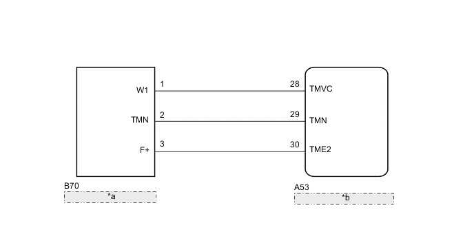
CHECK HARNESS AND CONNECTOR (ENGINE STOP AND START ECU - NEUTRAL POSITION SWITCH)
-
Disconnect the B70 neutral position switch connector and the A53 engine stop and start ECU connector.
-
Measure the resistance according to the value(s) in the table below.
Standard Resistance Tester Connection Condition Specified Condition A53-28 (TMVC) - B70-1 (W1) Always Below 1 Ω A53-29 (TMN) - B70-2 (TMN) Always Below 1 Ω A53-30 (TME2) - B70-3 (F+) Always Below 1 Ω A53-28 (TMVC) or B70-1 (W1) - Body ground Always 10 kΩ or higher A53-29 (TMN) or B70-2 (TMN) - Body ground Always 10 kΩ or higher A53-30 (TME2) or B70-3 (F+) - Body ground Always 10 kΩ or higher -
Reconnect the B70 neutral position switch connector and the A53 engine stop and start ECU connector.
NG
REPAIR OR REPLACE HARNESS OR CONNECTOR
OK
-
-
CHECK ENGINE STOP AND START ECU (TMN TERMINAL VOLTAGE)
-
Measure the voltage according to the value(s) in the table below.
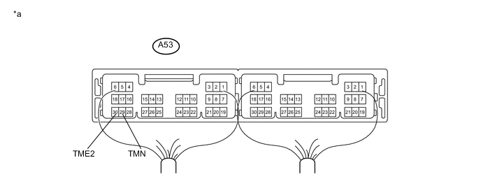
Text In Illustration *a Component with harness connected
(Engine Stop and Start ECU)
- - Standard Voltage Tester Connection Condition Specified Condition A53-29 (TMN) - A53-30 (TME2) Ignition switch ON, shift lever in neutral 2.7 to 4.3 V A53-29 (TMN) - A53-30 (TME2) Ignition switch ON, shift lever in any position other than neutral 0.7 to 1.9V
OK
REPLACE ENGINE STOP AND START ECU Click here
NG
REPLACE NEUTRAL POSITION SWITCH Click here
-