STOP AND START SYSTEM, Diagnostic DTC:P1539
| DTC Code | DTC Name |
|---|---|
| P1539 | AT Oil Pump |
DESCRIPTION
When the engine automatically stops, the front oil pump of the continuously variable transaxle assembly also stops.
For a smooth start of the vehicle, during the period between the engine automatic stop and vehicle restart, the oil pressure in the continuously variable transaxle assembly is maintained by operating the oil pump motor assembly.
The engine stop and start ECU switches the oil pump motor control relay to on with the output signal from the OPM2 terminal, supplies power to the oil pump motor assembly from the eco run vehicle converter assembly (backup boost converter), and operates the oil pump motor assembly with the output signal from the OPM1 terminal.
The state of the oil pump motor assembly is input to the engine stop and start ECU through the OPST signal line.
| DTC No. | Freeze Frame Data * | DTC Detection Condition | Trouble Area |
|---|---|---|---|
| P1539 | O/P Signal Fixed ON | The following condition continues for 2 seconds or more (1 trip detection logic):
|
Engine stop and start ECU |
| O/P Signal Fixed OFF | The following condition continues for 2 seconds or more (1 trip detection logic):
|
|
|
| O/P No Synchro Signal | The following condition continues for 2 seconds or more (1 trip detection logic):
|
|
|
| O/P Motor Curr Abnormal | The following condition continues for 2 seconds or more (1 trip detection logic):
|
|
*: Since each information can be confirmed by freeze frame data, record the freeze frame data before deleting the diagnosis code.
-
After troubleshooting, perform the following steps to recheck for DTCs and check if the Stop and Start system operates normally.
Tech Tips
-
If the battery terminal has been disconnected, the stop and start will be prohibited. In this case, drive the vehicle for 15 to 40 minutes to permit the stop and start operation.
-
Allow the engine to idle for 3 minutes after the engine warms up and check that the engine speed is within 50 rpm of the target idle speed.
-
Connect the intelligent tester to the DLC3.
-
Clear the DTCs Click here.
-
Start the engine and warm it up.
-
Drive the vehicle at 20 km/h (12.4 mph) or more.
-
Stop the vehicle, allow the engine to stop due to Stop and Start system control and wait for 3 seconds or more.
-
Release the brake pedal with the shift lever in D to allow the engine to restart.
Tech Tips
If the engine cranks slowly when the engine is restarted, it can be determined that battery voltage is low.
-
Check that no DTCs are output Click here.
-
-
Check if the Stop and Start system operates normally.
Tech Tips
-
If the battery terminal has been disconnected, the stop and start will be prohibited. In this case, drive the vehicle for 15 to 40 minutes to permit the stop and start operation.
-
Allow the engine to idle for 3 minutes after the engine warms up and check that the engine speed is within 50 rpm of the target idle speed.
-
Warm up the engine.
-
Turn the air conditioning system off.
-
Drive the vehicle at 7 km/h (4.3 mph) or more.
-
Stop the vehicle with the shift lever in D and depressed the brake pedal.
-
Check that the engine stops.
-
Release the brake pedal and check that the engine restarts.
-
WIRING DIAGRAM
Refer to DTC P1538 Click here.
CAUTION / NOTICE / HINT
Note
-
If the engine stop and start ECU is being replaced, register the previously recorded number of starter operations into the new engine stop and start ECU Click here.
-
After the engine stop and start ECU is replaced or after an air conditioner kit is installed, clear the A/C information stored in the engine stop and start ECU Click here.
-
When the engine stop and start ECU or components of the VSC system are replaced, initialization/obtainment of 0 point learning information is performed for the engine stop and start ECU Click here.
Tech Tips
-
DTCs for the Stop and Start system are not cleared even if the malfunction has been repaired. After repairing the malfunction, be sure to clear the DTCs Click here.
-
When P1538 and P1539 are simultaneously output, check P1538 first Click here.
PROCEDURE
-
CONFIRM DTC
-
Connect the intelligent tester to the DLC3.
-
Turn the ignition switch to ON.
-
Turn the tester on.
-
Check for DTCs and read the freeze frame data.
Result Result Proceed to Only DTC P1539 is output A DTC P1538 and P1539 are output B
B 
GO TO DTC CHART (P1538)
A 
-
-
READ FREEZE FRAME DATA
-
Connect the intelligent tester to the DLC3.
-
Turn the ignition switch to ON.
-
Turn the tester on.
-
Using the intelligent tester, confirm the vehicle conditions recorded in the freeze frame data which were present when the DTC was stored Click here.
Result Freeze Frame Data Item Proceed to "O/P Signal Fixed ON" is ON A "O/P Signal Fixed OFF" is ON B "O/P No Synchro Signal" is ON C "O/P Motor Curr Abnormal" is ON D
A
REPLACE ENGINE STOP AND START ECU Click here
C 
PERFORM ACTIVE TEST USING INTELLIGENT TESTER (Activate the AT Oil Pump (Lo)) Click here
D
PERFORM ACTIVE TEST USING INTELLIGENT TESTER (Activate the AT Oil Pump (Lo)) Click here
B
-
-
PERFORM ACTIVE TEST USING INTELLIGENT TESTER (Activate the AT Oil Pump (Lo))
-
Run the vehicle and warm up the engine and the continuously variable transaxle assembly.
-
Connect the intelligent tester to the DLC3.
-
Turn the ignition switch to ON.
-
Turn the tester on.
-
Enter the following menus: Powertrain / Stop and Start / Active Test / AT Oil Pump (Lo).
-
Connect an oscilloscope to the OPM1 and GND terminals of the engine stop and start ECU connector.
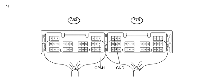
Text In Illustration *a Component with harness connected
(Engine stop and start ECU)
- - Item Condition Tester connection OPM1 - GND Tool setting 5 V/DIV, 5 ms/DIV Condition Active Test is in operation -
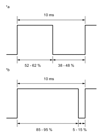
Text In Illustration *a Normal waveform *b Abnormal waveform Check the waveform when Active Test is in operation.
OK No noise to break the waveform is detected, and approximately 43% of the waveform are output. Result The state of the waveform Proceed to 38-48 %
(Normal waveform)
A There is a noise in the normal waveform. B 5-15 %
(Abnormal waveform)
C
B
REPAIR OR REPLACE NOISE SOURCE, HARNESS OR CONNECTOR
C
REPLACE ENGINE STOP AND START ECU Click here
A
-
-
INSPECT ENGINE STOP AND START ECU (OPST SIGNAL)
-
Connect an oscilloscope to the OPST and GND terminals of the engine stop and start ECU connector.
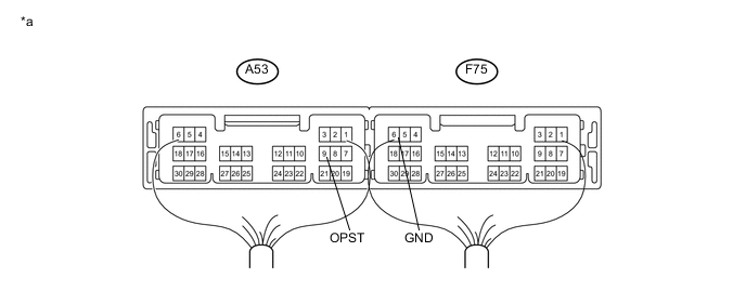
Text In Illustration *a Component with harness connected
(Engine stop and start ECU)
- - Item Condition Tester connection OPST - GND Tool setting 5 V/DIV, 5 ms/DIV Condition Active Test is in operation -
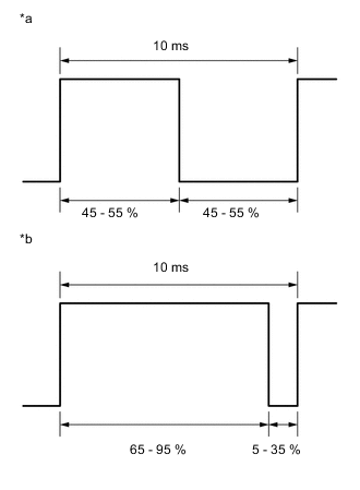
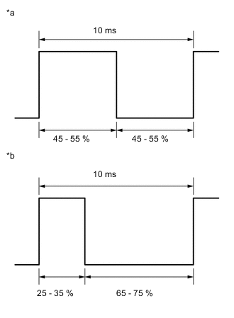
Text In Illustration *a Normal waveform *b Abnormal waveform Check the waveform when Active Test is in operation.
OK No noise to break the waveform is detected, and approximately 50% of the waveform are output. Result The state of the waveform Proceed to 45-55 %
(Normal waveform)
A There is a noise in the normal waveform. B 5-35 %
(Abnormal waveform)
C
A
REPLACE ENGINE STOP AND START ECU Click here
B
REPAIR OR REPLACE NOISE SOURCE, HARNESS OR CONNECTOR
C
REPLACE OIL PUMP WITH MOTOR ASSEMBLY Click here
-
-
PERFORM ACTIVE TEST USING INTELLIGENT TESTER (Activate the AT Oil Pump (Lo))
-
Run the vehicle and warm up the engine and the continuously variable transaxle assembly.
-
Connect the intelligent tester to the DLC3.
-
Turn the ignition switch to ON.
-
Turn the tester on.
-
Enter the following menus: Powertrain / Stop and Start / Active Test / AT Oil Pump (Lo).
-
Connect an oscilloscope to the OPST and GND terminals of the engine stop and start ECU connector.
Text In Illustration *a Component with harness connected
(Engine stop and start ECU)
- - Item Condition Tester connection OPST - GND Tool setting 5 V/DIV, 5 ms/DIV Condition Active Test is in operation -
Text In Illustration *a Normal waveform *b Abnormal waveform Check the waveform when Active Test is in operation.
OK No noise to break the waveform is detected, and approximately 50% of the waveform are output. Result The state of the waveform Proceed to 65-75 %
(Abnormal waveform)
A 45-55 %
(Normal waveform)
B There is a noise in the normal waveform. C
B
CLEAR DTC Click here
C
REPAIR OR REPLACE NOISE SOURCE, HARNESS OR CONNECTOR
A
-
-
READ VALUE USING INTELLIGENT TESTER (A/T OIL PRESSURE (CVT OIL PRESSURE))
-
Connect the intelligent tester to the DLC3.
-
Turn the ignition switch to ON.
-
Turn the tester on.
-
Enter the following menus: Powertrain / Engine and ECT / Data List.
-
In accordance with the display on the tester, read the Data List.
Tester Display Measurement Item/Range Normal Condition Diagnostic Note A/T Oil Pressure Secondary oil pressure value/
min.: -64 MPa
max.: 63.998 MPa
During idling stop
0.17 to 0.45 MPa
- Result Result Proceed to Data display is within Normal Condition range A Data display is not within Normal Condition range B
A
CHECK FOR INTERMITTENT PROBLEMS Click here
B
REPLACE OIL PUMP WITH MOTOR ASSEMBLY Click here
-
-
PERFORM ACTIVE TEST USING INTELLIGENT TESTER (Activate the AT Oil Pump (Lo))
-
Run the vehicle and warm up the engine and the continuously variable transaxle assembly.
-
Connect the intelligent tester to the DLC3.
-
Turn the ignition switch to ON.
-
Turn the tester on.
-
Enter the following menus: Powertrain / Stop and Start / Active Test / AT Oil Pump (Lo).
-
Connect an oscilloscope to the OPST and GND terminals of the engine stop and start ECU connector.
Text In Illustration *a Component with harness connected
(Engine stop and start ECU)
- - Item Condition Tester connection OPST - GND Tool setting 5 V/DIV, 5 ms/DIV Condition Active Test is in operation -
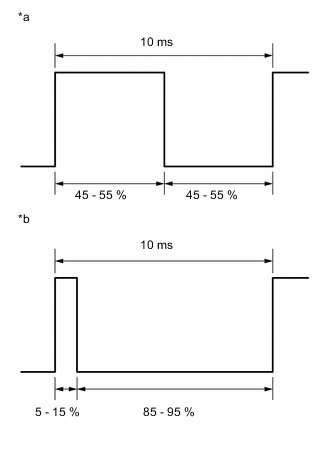
Text In Illustration *a Normal waveform *b Abnormal waveform Check the waveform when Active Test is in operation.
OK No noise to break the waveform is detected, and approximately 50% of the waveform are output. Result The state of the waveform Proceed to 45-55 %
(Normal waveform)
A There is a noise in the normal waveform. B 85-95 %
(Abnormal waveform)
C
B
REPAIR OR REPLACE NOISE SOURCE, HARNESS OR CONNECTOR
C
REPLACE OIL PUMP WITH MOTOR ASSEMBLY Click here
A
-
-
CLEAR DTC
Note
Before deleting the diagnosis code, be sure to store the freeze frame data.
-
Clear the DTC Click here.
NEXT
-
-
PERFORM ACTIVE TEST USING INTELLIGENT TESTER (Activate the AT Oil Pump (Lo))
-
Run the vehicle and warm up the engine and the continuously variable transaxle assembly.
-
Connect the intelligent tester to the DLC3.
-
Turn the ignition switch to ON.
-
Turn the tester on.
-
Enter the following menus: Powertrain / Stop and Start / Active Test / AT Oil Pump (Lo).
-
Connect an oscilloscope to the OPST and GND terminals of the engine stop and start ECU connector.
Text In Illustration *a Component with harness connected
(Engine stop and start ECU)
- - Item Condition Tester connection OPST - GND Tool setting 5 V/DIV, 5 ms/DIV Condition Active Test is in operation -
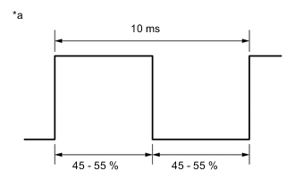
Text In Illustration *a Normal waveform Check the waveform when Active Test is in operation.
OK No noise to break the waveform is detected, and approximately 50% of the waveform are output.
NG
REPLACE OIL PUMP WITH MOTOR ASSEMBLY Click here
OK
-
-
CONFIRM DTC OUTPUT
-
Connect the intelligent tester to the DLC3.
-
Turn the ignition switch to ON.
-
Start the engine.
-
Drive the vehicle with a stop-and-go city drive pattern for more than 15 minutes.
-
Enter the following menus: Powertrain / Stop and Start / DTC.
-
Confirm that the DTC is not output again.
Result Result Proceed to DTC P1539 is output A DTC is not output B Tech Tips
When the diagnosis code is not displayed, there is a possibility that the oil pump motor cannot run because of a blockage in the hydraulic circuit temporarily.
B
END
A
-
-
READ VALUE USING INTELLIGENT TESTER (A/T OIL PRESSURE (CVT OIL PRESSURE))
-
Connect the intelligent tester to the DLC3.
-
Turn the ignition switch to ON.
-
Turn the tester on.
-
Enter the following menus: Powertrain / Engine and ECT / Data List.
-
In accordance with the display on the tester, read the Data List.
Tester Display Measurement Item/Range Normal Condition Diagnostic Note A/T Oil Pressure Secondary oil pressure value/
min.: -64 MPa
max.: 63.998 MPa
During idling stop
0.17 to 0.45 MPa
- Result Result Proceed to Data display is within Normal Condition range A Data display is not within Normal Condition range B
A
REPLACE ENGINE STOP AND START ECU Click here
B
REPLACE OIL PUMP WITH MOTOR ASSEMBLY Click here
-