STOP AND START SYSTEM, Diagnostic DTC:P1538
| DTC Code | DTC Name |
|---|---|
| P1538 | Circuit Malfunction between AT Oil Pump and Stop and Start ECU |
DESCRIPTION
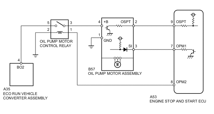
When the engine automatically stops, the front oil pump of the continuously variable transaxle assembly also stops.
For a smooth start of the vehicle, during the period between the engine automatic stop and vehicle restart, the oil pressure in the continuously variable transaxle assembly is maintained by operating the oil pump motor assembly.
The engine stop and start ECU switches the oil pump motor control relay to on with the output signal from the OPM2 terminal, supplies power to the oil pump motor assembly from the eco run vehicle converter assembly (backup boost converter), and operates the oil pump motor assembly with the output signal from the OPM1 terminal.
| DTC No. | Freeze Frame Data * | DTC Detection Condition | Trouble Area |
|---|---|---|---|
| P1538 | O/P Circuit/Relay Error | The following condition continues for 2 seconds or more (1 trip detection logic):
|
|
| O/P Signal GND Short | The following condition continues for 2 seconds or more (1 trip detection logic):
|
|
|
| O/P Signal Open/Short | The following condition continues for 2 seconds or more (1 trip detection logic):
|
|
|
| O/P Relay Malfunction | The following condition continues for 2 seconds or more (1 trip detection logic):
|
|
*: Since each information can be confirmed by freeze frame data, record the freeze frame data before deleting the diagnosis code.
Tech Tips
DTCs for the Stop and Start system are not cleared even if the malfunction has been repaired. After repairing the malfunction, be sure to clear the DTCs Click here.
-
After troubleshooting, perform the following steps to recheck for DTCs and check if the Stop and Start system operates normally.
Tech Tips
-
If the battery terminal has been disconnected, the stop and start will be prohibited. In this case, drive the vehicle for 15 to 40 minutes to permit the stop and start operation.
-
Allow the engine to idle for 3 minutes after the engine warms up and check that the engine speed is within 50 rpm of the target idle speed.
-
Connect the intelligent tester to the DLC3.
-
Clear the DTCs Click here.
-
Start the engine and warm it up.
-
Drive the vehicle at 20 km/h (12.4 mph) or more.
-
Stop the vehicle, allow the engine to stop due to Stop and Start system control and wait for 3 seconds or more.
-
Release the brake pedal with the shift lever in D to allow the engine to restart.
Tech Tips
If the engine cranks slowly when the engine is restarted, it can be determined that battery voltage is low.
-
Check that no DTCs are output Click here.
-
-
Check if the Stop and Start system operates normally.
Tech Tips
-
If the battery terminal has been disconnected, the stop and start will be prohibited. In this case, drive the vehicle for 15 to 40 minutes to permit the stop and start operation.
-
Allow the engine to idle for 3 minutes after the engine warms up and check that the engine speed is within 50 rpm of the target idle speed.
-
Warm up the engine.
-
Turn the air conditioning system off.
-
Drive the vehicle at 7 km/h (4.3 mph) or more.
-
Stop the vehicle with the shift lever in D and depressed the brake pedal.
-
Check that the engine stops.
-
Release the brake pedal and check that the engine restarts.
-
WIRING DIAGRAM
CAUTION / NOTICE / HINT
Note
-
If the engine stop and start ECU is being replaced, register the previously recorded number of starter operations into the new engine stop and start ECU Click here.
-
After the engine stop and start ECU is replaced or after an air conditioner kit is installed, clear the A/C information stored in the engine stop and start ECU Click here.
-
After the engine stop and start ECU or airbag sensor assembly (yaw rate sensor) is replaced, initialize and calibrate 0 point of deceleration sensor Click here.
Tech Tips
-
DTCs for the Stop and Start system are not cleared even if the malfunction has been repaired. After repairing the malfunction, be sure to clear the DTCs Click here.
-
When P1538 and P1539 are simultaneously output, check P1538 first Click here.
PROCEDURE
-
READ FREEZE FRAME DATA
-
Connect the intelligent tester to the DLC3.
-
Turn the ignition switch to ON.
-
Turn the tester on.
-
Using the intelligent tester, confirm the vehicle conditions recorded in the freeze frame data which were present when the DTC was stored Click here.
Result Freeze Frame Data Item Proceed to "O/P Circuit/Relay Error" is ON A "O/P Signal GND Short" is ON B "O/P Signal Open/Short" is ON C "O/P Relay Malfunction" is ON D
B 
CHECK HARNESS AND CONNECTOR (ENGINE STOP AND START ECU - OIL PUMP MOTOR ASSEMBLY) Click here
C
CHECK HARNESS AND CONNECTOR (ENGINE STOP AND START ECU - OIL PUMP MOTOR ASSEMBLY) Click here
D
INSPECT OIL PUMP MOTOR CONTROL RELAY Click here
A 
-
-
PERFORM ACTIVE TEST USING INTELLIGENT TESTER (Activate the AT Oil Pump (Lo))
Note
Be sure to perform Active Test after the engine is warmed up, since the oil pump motor cannot operate normally when the CVT fluid temperature is low.
-
Connect the intelligent tester to the DLC3.
-
Turn the ignition switch to ON.
-
Turn the tester on.
-
Enter the following menus: Powertrain / Stop and Start / Active Test / AT Oil Pump (Lo).
-
During engine stop, turn the ignition switch to ON, and perform Active Test to confirm an operating sound and vibration from the oil pump.
Standard AT Oil Pump (Lo) Operating sound and vibration ON Heard and felt OFF Unheard and unfelt
NG
CHECK HARNESS AND CONNECTOR (ECO RUN VEHICLE CONVERTER - OIL PUMP MOTOR CONTROL RELAY) Click here
OK
-
-
INSPECT ENGINE STOP AND START ECU
-
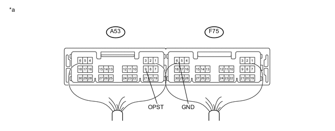
Connect an oscilloscope to the OPST and GND terminals of the engine stop and start ECU connector.
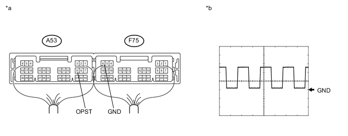
Text In Illustration *a Component with harness connected
(Engine stop and start ECU)
*b Waveform -
Start the engine.
-
Check the signal waveform according to the condition(s) in the table below.
Item Condition Tester connection OPST - GND Tool setting 5 V/DIV, 5 ms/DIV Condition Engine stopped due to stop and start system control with the shift lever in D OK A rectangular waveform similar to that shown in the illustration is output, and no noise is heard and no vibration is felt.
OK 
REPLACE ENGINE STOP AND START ECU Click here
NG
-
-
INSPECT OIL PUMP MOTOR ASSEMBLY (OPST TERMINAL VOLTAGE)
-
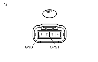
Text In Illustration *a Front view of wire harness connector
(to oil pump motor assembly)
Disconnect the B57 oil pump motor assembly connector.
-
Turn the ignition switch to ON.
-
Measure the voltage according to the value(s) in the table below.
Standard Voltage Tester Connection Condition Specified Condition B57-2 (OPST) - B57-1 (GND) Ignition switch ON 8 to 14 V
OK
REPLACE OIL PUMP WITH MOTOR ASSEMBLY Click here
NG
-
-
CHECK HARNESS AND CONNECTOR (ENGINE STOP AND START ECU - OIL PUMP MOTOR ASSEMBLY)
-
Disconnect the A53 engine stop and start ECU connector.
-
Disconnect the B57 oil pump motor assembly connector.
-
Measure the resistance according to the value(s) in the table below.
Standard Resistance Tester Connection Condition Specified Condition A53-9 (OPST) - B57-2 (OPST) Always Below 1 Ω A53-9 (OPST) - Body ground Always 10 kΩ or higher B57-2 (OPST) - Body ground Always 10 kΩ or higher
OK
REPLACE ENGINE STOP AND START ECU Click here
NG
REPAIR OR REPLACE HARNESS OR CONNECTOR
-
-
CHECK HARNESS AND CONNECTOR (ECO RUN VEHICLE CONVERTER - OIL PUMP MOTOR CONTROL RELAY)
-
Remove the oil pump motor control relay from the engine room sub relay block.
-
Disconnect the A35 eco run vehicle converter assembly connector.
-
Measure the resistance according to the value(s) in the table below.
Standard Resistance Tester Connection Condition Specified Condition A35-4 (BO2) - oil pump motor control relay terminal 5 Always Below 1 Ω oil pump motor control relay terminal 5 - Body ground Always 10 kΩ or higher A35-4 (BO2) - Body ground Always 10 kΩ or higher
NG
REPAIR OR REPLACE HARNESS OR CONNECTOR
OK
-
-
OIL PUMP MOTOR CONTROL RELAY (+B TERMINAL VOLTAGE)
-
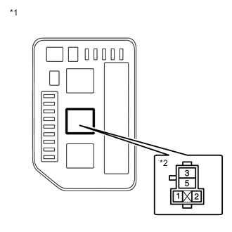
Text In Illustration *1 Engine room sub relay block *2 Oil pump motor control relay Holder Remove the oil pump motor control relay from the engine room sub relay block.
-
Measure the voltage according to the value(s) in the table below.
Standard Voltage Tester Connection Condition Specified Condition oil pump motor control relay terminal 5 - Body ground Ignition switch ON 8 to 14 V
NG
REPLACE ECO RUN VEHICLE CONVERTER ASSEMBLY Click here
OK
-
-
INSPECT OIL PUMP MOTOR CONTROL RELAY
-
Remove the oil pump motor control relay from the engine room sub relay block.
-
Measure the resistance according to the value(s) in the table below.
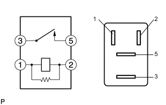
Standard Resistance Tester Connection Condition Specified Condition 3 - 5 Battery voltage not applied 10 kΩ or higher 3 - 5 Battery voltage applied to terminals 1 and 2 Below 1 Ω
NG
REPLACE OIL PUMP MOTOR CONTROL RELAY
OK
-
-
CHECK HARNESS AND CONNECTOR (ENGINE STOP AND START ECU - OIL PUMP MOTOR CONTROL RELAY)
-
Remove the oil pump motor control relay from the engine room sub relay block.
-
Disconnect the A53 engine stop and start ECU connector.
-
Measure the resistance according to the value(s) in the table below.
Standard Resistance Tester Connection Condition Specified Condition A53-8 (OPM2) - oil pump motor control relay terminal 1 Always Below 1 Ω oil pump motor control relay terminal 1 - Body ground Always 10 kΩ or higher A53-8 (OPM2) - Body ground Always 10 kΩ or higher oil pump motor control relay terminal 2 - Body ground Always Below 1 Ω
NG
REPAIR OR REPLACE HARNESS OR CONNECTOR
OK
-
-
CHECK HARNESS AND CONNECTOR (OIL PUMP MOTOR CONTROL RELAY - OIL PUMP MOTOR ASSEMBLY)
-
Disconnect the B57 oil pump motor assembly connector.
-
Remove the oil pump motor control relay from the engine room sub relay block.
-
Measure the resistance according to the value(s) in the table below.
Standard Resistance Tester Connection Condition Specified Condition B57-4 (+B) - oil pump motor control relay terminal 3 Always Below 1 Ω oil pump motor control relay terminal 3 - Body ground Always 10 kΩ or higher B57-4 (+B) - Body ground Always 10 kΩ or higher B57-1 (GND) - Body ground Always Below 1 Ω
OK
REPLACE OIL PUMP WITH MOTOR ASSEMBLY Click here
NG
REPAIR OR REPLACE HARNESS OR CONNECTOR
-
-
CHECK HARNESS AND CONNECTOR (ENGINE STOP AND START ECU - OIL PUMP MOTOR ASSEMBLY)
-
Disconnect the A53 engine stop and start ECU connector.
-
Disconnect the B57 oil pump motor assembly connector.
-
Measure the resistance according to the value(s) in the table below.
Standard Resistance Tester Connection Condition Specified Condition A53-9 (OPST) - B57-2 (OPST) Always Below 1 Ω A53-9 (OPST) - Body ground Always 10 kΩ or higher B57-2 (OPST) - Body ground Always 10 kΩ or higher
NG
REPAIR OR REPLACE HARNESS OR CONNECTOR
OK
-
-
INSPECT ENGINE STOP AND START ECU (OPST TERMINAL VOLTAGE)
-
Disconnect the A53 engine stop and start ECU connector.
-
Turn the ignition switch to ON.
-
Measure the voltage according to the value(s) in the table below.
Text In Illustration *a Component with harness connected
(Engine stop and start ECU)
- - Standard Voltage Tester Connection Condition Specified Condition A53-9 (OPST) - F75-6 (GND) Ignition switch ON 8 to 14 V
OK
REPLACE OIL PUMP WITH MOTOR ASSEMBLY Click here
NG
REPLACE ENGINE STOP AND START ECU Click here
-
-
CHECK HARNESS AND CONNECTOR (ENGINE STOP AND START ECU - OIL PUMP MOTOR ASSEMBLY)
-
Disconnect the A53 engine stop and start ECU connector.
-
Disconnect the B57 oil pump motor assembly connector.
-
Measure the resistance according to the value(s) in the table below.
Standard Resistance Tester Connection Condition Specified Condition A53-7 (OPM1) - B57-3 (SI) Always Below 1 Ω A53-7 (OPM1) - Body ground Always 10 kΩ or higher B57-3 (SI) - Body ground Always 10 kΩ or higher
NG
REPAIR OR REPLACE HARNESS OR CONNECTOR
OK
-
-
INSPECT OIL PUMP MOTOR ASSEMBLY (SI TERMINAL VOLTAGE)
-
Disconnect cable from negative battery terminal.
-
Remove the oil pump motor control relay from the engine room sub relay block.
-
Connect terminals between 3 and 5 of the oil pump motor control relay in the engine room sub relay block side.
Tech Tips
When connecting terminals, use the wire harness with a diameter more than 1.25mm.
-
Connect cable to negative battery terminal.
-
Measure the voltage according to the value(s) in the table below.
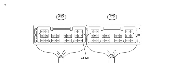
Text In Illustration *a Component with harness connected
(Engine stop and start ECU)
- - Standard Voltage Tester Connection Condition Specified Condition A53-7 (OPM1) - Body ground When connecting terminals between 3 and 5 of the oil pump motor control relay in the engine room sub relay block side 8 to 14 V
OK
REPLACE ENGINE STOP AND START ECU Click here
NG
REPLACE OIL PUMP WITH MOTOR ASSEMBLY Click here
-
-
INSPECT OIL PUMP MOTOR CONTROL RELAY
-
Remove the oil pump motor control relay from the engine room sub relay block.
-
Measure the resistance according to the value(s) in the table below.
Standard Resistance Tester Connection Condition Specified Condition 3 - 5 Battery voltage not applied 10 kΩ or higher 3 - 5 Battery voltage applied to terminals 1 and 2 Below 1 Ω
NG
REPLACE OIL PUMP MOTOR CONTROL RELAY
OK
-
-
CHECK HARNESS AND CONNECTOR (OIL PUMP MOTOR CONTROL RELAY - OIL PUMP MOTOR ASSEMBLY)
-
Disconnect the B57 oil pump motor assembly connector.
-
Remove the oil pump motor control relay from the engine room sub relay block.
-
Measure the resistance according to the value(s) in the table below.
Standard Resistance Tester Connection Condition Specified Condition B57-4 (+B) - Body ground Always 10 kΩ or higher oil pump motor control relay terminal 3 - Body ground Always 10 kΩ or higher
NG
REPAIR OR REPLACE HARNESS OR CONNECTOR
OK
-
-
CHECK HARNESS AND CONNECTOR (ENGINE STOP AND START ECU - OIL PUMP MOTOR CONTROL RELAY)
-
Remove the oil pump motor control relay from the engine room sub relay block.
-
Disconnect the A53 engine stop and start ECU connector.
-
Measure the resistance according to the value(s) in the table below.
Standard Resistance Tester Connection Condition Specified Condition A53-8 (OPM2) - Body ground Always 10 kΩ or higher Oil pump motor control relay terminal 1 - Body ground Always 10 kΩ or higher
OK
REPLACE ENGINE STOP AND START ECU Click here
NG
REPAIR OR REPLACE HARNESS OR CONNECTOR
-