STOP AND START SYSTEM DATA LIST / ACTIVE TEST
-
DATA LIST
Tech Tips
Using the intelligent tester to read the Data List allows the values or states of switches, sensors, actuators and other items to be read without removing any parts. This non-intrusive inspection can be very useful because intermittent conditions or signals may be discovered before parts or wiring is disturbed. Reading the Data List information early in troubleshooting is one way to save diagnostic time.
Note
In the table below, the values listed under "Normal Condition" are reference values. Do not depend solely on these reference values when deciding whether a part is faulty or not.
-
Warm up the engine.
-
Turn the ignition switch off.
-
Connect the intelligent tester to the DLC3.
-
Start the engine.
-
Turn the tester on.
-
Enter the following menus: Powertrain / Stop and Start / Data List.
-
Check the values by referring to the table below.
Tech Tips
The results of a test performed on an actual vehicle are shown in the "Result of Real-vehicle Check" column. Use these values as a reference.
Stop and Start System Tester Display Measurement Item/Range Normal Condition Result of Real-vehicle Check Diagnostic Note Eco Warning Stop and start cancel indicator light status:
ON/OFF
OFF: Stop and start cancel indicator light OFF or ON (not blinking) under system normal operation OFF: Stop and start cancel indicator light OFF ON: Any malfunction occurs in the system and the indicator light is blinking. Coolant Temp Engine coolant temperature:
Min.: 16°C (60.8°F), Max.: 127°C (260.6°F)
75 to 95°C (167 to 203°F): Idling after engine warmed up 85°C (185°F): Idling after engine warmed up This is sent from the ECM. Engine Spd (ECM) Engine speed signal from ECM through CAN communication:
Min.: 0 rpm, Max.: 12800 rpm
600 to 700 rpm: Idling after engine warmed up*2
550 to 650 rpm: Idling after engine warmed up*3
650 rpm: Idling after engine warmed up*2
600 rpm: Idling after engine warmed up*3
This is sent from the ECM. Engine Spd (NE Signal) Engine speed signal (calculated from pulse signal):
Min.: 0 rpm, Max.: 25600 rpm
600 to 700 rpm: Idling after engine warmed up*2
550 to 650 rpm: Idling after engine warmed up*3
650 rpm: Idling after engine warmed up*2
600 rpm: Idling after engine warmed up*3
The pulse signal is from NEO terminal of the ECM. Deceleration Sens Offset Val Deceleration sensor offset value:
Min.: -1176.008 m/s2, Max.: 1176.007 m/s2
-0.903 to 0.903: after the deceleration sensor 0 point learning completion -0.5 to 0.5 m/s2: after the calibration of deceleration sensor offset
- Deceleration Sens Calibration Deceleration sensor calibration status:
Incompl / Running / Compl / Err1 / Err2 / Err3
Compl: after the deceleration sensor 0 point learning completion Compl: after the deceleration sensor 0 point learning completion - Gradient of Road Surface Degree of load gradient:
Min.: -10.24 m/s2, Max.: 10.16 m/s2
-0.1 to 0.1 m/s2: stop vehicle on level surface
Approx. 0 m/s2: stop vehicle on level surface
- Battery Voltage Battery voltage:
Min.: 0 V, Max.: 20 V
11 to 14 V: Idling 12.5 V: Idling stop condition - Battery Temp (Start) Battery temperature:
Min.: -40°C (-40°F), Max.: 100°C (212°F)
Close to actual temperature 25°C (77°F): Idling stop condition - A/C Outlet Temp A/C blower temperature:
Min.: -159°C (-254.2°F), Max.: 159°C (318.2°F)
Close to actual temperature 25°C (77°F): Idling stop condition Measured by duct air temperature sensor (cooler thermistor). Oper Permission (CVT) Stop and start control availability state from CVT requirement:
ON/OFF
ON: Preconditions for Stop and Start system control have been met ON: During idling stop due to stop and start control. Receives information from the engine control computer through CAN communication Engine Type Information Information on the engine type form the EFI system
Avail/Not Avi
Information of the engine type received from the engine ECU through CAN communication Avail Receives information from the engine control computer through CAN communication D Courtesy Switch Signal Driver door courtesy switch signal:
ON/OFF
ON: Driver door open OFF: Driver side door closed - Hood Courtesy Switch Hood courtesy switch signal:
ON/OFF
ON: Engine hood closed ON: Engine hood closed - Neutral Switch Neutral position switch signal:
ON/OFF
ON: Shift lever in N or P*2
ON: Shift lever in neutral*3
ON: Shift lever in neutral - Clutch Upper SW Clutch switch (upper) signal:
ON/OFF
ON: Clutch pedal fully released ON: Clutch pedal released - Clutch Lower SW Clutch start switch (lower) signal:
ON/OFF
ON: Clutch pedal fully depressed OFF: Clutch pedal released - Starter Cranking operation status:
ON/OFF
ON: Cranking - - TC Terminal TC and CG terminals of DLC3:
ON/OFF
ON: TC and CG terminals of DLC3 are connected OFF: TC terminal not grounded - Cancel Switch Stop and start cancel switch signal:
ON/OFF
ON: Cancel switch pressed (ON) OFF: Cancel switch not pressed (OFF) - IG Switch Ignition switch signal:
ON/OFF
ON: Ignition switch ON ON: Ignition switch ON - Idle Engine idling status:
ON/OFF
ON: Engine running with throttle closed ON: Engine running with throttle closed This is sent from the ECM. Starter Input Signal Starter input signal:
ON/OFF
ON: Starter relay being supplied with power OFF: Ignition switch ON Starter drive signal at engine restart Engine Start (IG SW) Manual engine starting method:
ON/OFF
ON: Engine started by ignition switch operation OFF: Ignition switch ON Starter operated due to driver key operation Stop Light SW (ECM) Stop light switch signal:
ON/OFF
ON: Stop lights ON OFF: Brake pedal released This signal is sent from the ECM. Stop Light SW (ABS/VSC) Stop light switch signal:
ON/OFF
ON: Stop lights ON OFF: Brake pedal released This signal is sent from the ABS/VSC. Engine Starter Signal Starter signal status:
ON/OFF
ON: Cranking OFF: IG ON This signal is sent from the ECM. Buzzer Buzzer status:
ON/OFF
ON: Buzzer ON OFF: Buzzer does not sound Refer to System Description Click here.
Indicat. Light Eco Stop and start indicator light status:
ON/OFF
ON: Stop and start indicator light ON or blinking ON: Engine stopped due to Stop and Start system control - Starter Request Starter operation request signal:
ON/OFF
ON: Starter operated by engine stop and start ECU ON: Requested engine restart - Oil Prs Warn Light Prohibit Oil pressure warning light status:
Permit/Prohibit
Prohibit: Prohibiting from lighting Prohibit: During idling stop due to stop and start control Engine stop and start ECU informs combination meter assembly that oil pressure warning light does not come on during engine stopped due to stop and start system control. Brake Press Hold Req Brake press hold operation request:
ON/OFF
- ON: With shift lever in D, during idling stop due to stop and start control ON remains displayed when the brake pressure hold is required during idling stop due to stop and start control. Fail Mode Detection Fail mode detection output signal:
ON/OFF
- OFF: System normal - S&S Cancel Light Code Transmission code from the engine stop and start ECU to the combination meter:
0: extinction / 1: lighting / 2: blink / 3: - / 4: DTC output
- 0: System normal - Starter Operation # Number of starter operations (count record):
Min.: 0, Max.: 1048575
- 5182: Reference - Vehicle Spd 1 (ABS/VSC) Vehicle speed signal from skid control ECU (through CAN communication):
Min.: 0 km/h (0 mph), Max.: 327.67 km/h (203.6 mph)
0 km/h (0 mph): Vehicle stopped 0 km/h (0 mph): Idling stop condition - Vehicle Spd 4 (Calc Value) Vehicle speed signal for diagnosis (calculated from pulse signal):
Min.: 0 km/h (0 mph), Max.: 327.67 km/h (203.6 mph)
0 km/h (0 mph): Vehicle stopped 0 km/h (0 mph): Idling stop condition - Battery Current Battery current:
Min.: -125 A, Max.: 124.99 A
Battery discharge current -6.38 A: Engine stopped due to Stop and Start system control - Brake Boost Pressure Brake booster pressure (absolute pressure):
Min.: 0 kPa (0 mmHg), Max.: 112 kPa (840 mmHg)
Approx. 100 kPa (750 mmHg): Ignition switch ON, brake pedal depressed several times (differs according to atmospheric pressure) 30 kPa (225 mmHg): Idling stop condition - Brake Negative Pressure Brake booster vacuum (negative pressure):
Min.: 0 kPa (0 mmHg), Max.: 640 kPa (4800 mmHg)
Approx. 0 kPa (0 mmHg): Ignition switch ON, brake pedal depressed several times 73.22 kPa (549 mmHg): Idling stop condition
(Brake Negative Pressure = Estimated atmospheric pressure - Brake Boost Pressure)
This item cannot be checked if an error occurs in communication with the ECM. Ambient Temp Sensor Ambient temperature:
Min.: -80°C (-112°F), Max.: 80°C (176°F)
Close to ambient air temperature 25.0°C (77°F): Reference - Stop&Start of Eng State Stop and Start system control status:
IG / Run / Stopreq / Stop / Restart
-
IG: Before engine started
-
Run: Engine running
-
Stopreq: Engine stop requested
-
Stop: Engine stopped
-
Restart: Engine restarted
Stop: Engine stopped due to Stop and Start system control - Idling Stop Rate Rate of the idling stop time to the entire ignition ON time:
Min.: 0 %, Max.: 100 %
- - - Integrated Current
*1
Battery integrated current calculated from the battery current sensor signal:
Min.: -268434.45 A-sec, Max.: 268435.45 A-sec
Differs according to the vehicle condition (charge/discharge conditions) 1349.36 A-sec: Engine stopped due to Stop and Start system control Refer to "Regarding Battery Integrated Current" below for details. Cranking Time Engine cranking time (in present trip):
Min.: 0 ms, Max.: 134215 ms
0.3 to 0.5 seconds: Starter on time due to Stop and Start system control 391.16 ms: Engine stopped due to Stop and Start system control When the minimum voltage is detected during engine cranking Min Voltage (Cranking) Minimum battery voltage while engine cranking (in present trip):
Min.: 0 V, Max.: 20.0 V
6 to 10 V 10.23 V Lowest battery voltage measured in a 5 second period after the starter starts operating. Min Volt (After Cranking) Minimum battery voltage just after engine cranking:
Min.: 0 V, Max.: 20.0 V
6 to 10 V 9 V Minimum battery voltage while starter driving Master Cylinder Pressure Master Cylinder Pressure:
Min.: 0 MPa, Max.: 393.2 MPa
0 to 5 MPa Approx. 1MPa: Brake on - State of BBC Backup boost converter status (diagnostic result):
Cycle Err / Overvol / Overload / Normal / Low Vol / Duty Err
Normal: Backup boost converter operating normally Normal: Engine stopped due to Stop and Start system control
-
Duty Err:
-
Inappropriate DDON duty value is detected.
-
Cycle Err:
-
DDON duty cycle deviates beyond the allowable range.
-
Low Vol:
-
A decrease in the voltage of the control IC power source within the backup boost converter is detected when ignition switch is ON.
-
Overload:
-
Overcurrent is detected such as an audio excessive volume.
-
Overvol:
-
When the ignition switch is ON:
-
Overvoltage is detected at the control IC power source within the backup boost converter.
-
Overheating is detected at the control IC power source within the backup boost converter.
-
When boosting:
-
Error is detected in the feedback circuit in the backup boost converter.
-
Too high or low output voltage.
Refer to DTC P323B.
BBC Check Result Backup boost converter over-load status (fuse function status):
Normal/Abnormal
Normal: Backup boost converter operating normally Normal: Engine stopped due to Stop and Start system control Excessive amperage load when the backup boost converter is boosting the voltage during engine restart. Atmosphere Pressure Atmospheric pressure (calculated value):
Min.: 0 kPa (0 mmHg), Max.: 255 kPa (1913 mmHg)
Approx. 100 kPa (750 mmHg): Ignition switch ON (close to actual atmospheric pressure) 103 kPa (775 mmHg): Engine stopped due to Stop and Start system control ECM calculated value EPS Load Electric power steering current:
Min.: -327.68 A, Max.: 327.67 A
Approx. 0 A: EPS assist is not activated 0.02 A: Engine stopped due to Stop and Start system control - Accelerator Position Accelerator pedal opening:
Min.: 0 %, Max.: 127.5 %
0 %: Accelerator pedal fully released 0.0 %: Accelerator pedal fully released ECM calculated value Shift Position Shift position status:
Unset / B / D / R / N / P
Shift position is indicated P: Vehicle stopped with the shift lever in P - Engine OFF Request Engine stop request:
ON/OFF
ON: Stop and Start system control activated ON: Engine stopped due to Stop and Start system control ON is shown when fuel cut is performed due to Stop and Start system control, engine start is not requested, engine is stopped, or starter is forced to operate. Wrong Operation (Start) Wrong operation for engine start:
ON/OFF
ON: Shift lever is moved from P or N to the driving position without depressing the brake pedal while the engine is stopped due to stop and start control*2
ON: Shift lever operated without depressing clutch pedal while the engine is stopped due to Stop and Start system control*3
OFF: During idling stop due to stop and start control. - Engine Reverse Rev. Engine reverse revolution status:
ON/OFF
ON: Engine turning in reverse direction OFF: During idling stop due to stop and start control. This is sent from the ECM. Blower Switch A/C blower switch status:
ON/OFF
ON: Blower fan operating OFF: Blower switch off - N/Clutch Lower SW Abnoml*3 Neutral position switch and clutch start switch (lower) malfunction detection status:
ON/OFF
ON: Neutral position switch or clutch start switch (lower) malfunction OFF: During idling stop due to stop and start control. - N/Clutch Upper SW Abnoml*3 Neutral position switch and clutch switch (upper) malfunction detection status:
ON/OFF
ON: Neutral position switch or clutch switch (lower) malfunction OFF: During idling stop due to stop and start control. - Permit Idling Stop Engine stop standby:
ON/OFF
ON: Stop and Start system control is available OFF: During idling stop due to stop and start control.
Before vehicle stopped after on condition is met
- Running History Vehicle driving record:
ON/OFF
ON: The history of the vehicle was driven at 2 km/h (1.2 mph) or more after engine is started or restarted (with no DTC stored) ON: Before vehicle stopped after on condition is met It turns off when the engine is stopped by stop and start control or when the shift lever is moved from the driving position to P, N or R. Auto A/C Whether vehicle is equipped with auto or manual air conditioning:
Without/With
Without: Not equipped with auto or manual air conditioning
With: Equipped with auto or manual air conditioning
With: with auto or manual air conditioning system A/C information needs to be registered after ECU replacement Click here.
A/C Request Engine start request from A/C system:
ON/OFF
ON: A/C needs engine running to maintain required A/C performance OFF: During idling stop due to stop and start control. Measured by duct air temperature sensor (cooler thermistor)
A/C performance or depending on A/C switch or blower switch or defroster switch.
Wheel Speed Malfunction Wheel Speed Malfunction status:
ON/OFF
OFF: Input value from speed sensor is normal OFF: After driving or during parking ON remains displayed when any input values from the speed sensors are abnormal. Slip History Vehicle slip record:
Without/With
- - - EEPROM Writing Failure EEPROM writing failure status:
ON/OFF
OFF: Writing into EEPROM has succeeded. OFF: Idling ON remains displayed when writing into EEPROM has failed
(when writing into EEPROM has succeeded, it is cleared)
E/G ECU Region Mismatch E/G ECU region mismatch status:
ON/OFF
OFF: Engine ECU destination information is matched. OFF: IG ON ON remains displayed when the engine ECU for regions destinations without the stop and start system settings is detected. Oil Pump Relay Oil pump relay status:
ON/OFF
ON: Oil pump relay ON ON: During idling stop due to stop and start control ON: On remains displayed while the engine is stopped due to stop and start control Oil Pump Status Oil pump status:
ON/OFF
- ON: During idling stop due to stop and start control with the shift lever in D ON remains displayed when the oil pump is in operation. Oil Pump Duty Oil pump duty:
Min.: 0 %, Max.: 100 %
Approx. 65%: when the oil pump drives during the engine is stopped due to the stop and start control with the shift lever in D. Approx. 65%: ON: During idling stop due to stop and start control with the shift lever in D. - State of Oil Pump State of oil pump status:
Cir Err / Stop / Starting / Running / Sig1 Err / Not Sync / Vol Err / Cur Err / Sig2 Err
Running: Motor runs normally Running: During idling stop due to stop and start control with the shift lever in D. Cir Err: OPST circuit open/+B short or the power supply relay is off
Stop: Motor stops normally
Starting: Motor is starting
Running: Motor is running normally
Sig1 Err: Imperfect SIG signal
Not sync: Imperfect motor start / loss of synchronism
Vol Err: Abnormal power supply voltage
Cur Err: Abnormal power supply current
Sig2 Err: OPST signal GND short circuit
Shift D position Shift lever in D condition for stop and start control:
ON/OFF
ON: Preconditions for Stop and Start system control have been met ON: Vehicle is stopped from running by depressing the brake pedal, with the shift lever in D. - Neutral Switch Neutral condition for stop and start control:
ON/OFF
ON: After driving in driving position, when the shift lever is moved to P or N.*2
ON: After driving with the shift lever in driving position, when the neutral position is detected and the clutch pedal is fully released.*3
ON: During idling stop due to stop and start control with the shift lever in P or N*2
ON: During idling stop due to stop and start control*3
- Idling Engine idling condition for stop and start control:
ON/OFF
ON: Engine running (engine speed is 1000 rpm or less), and throttle valve fully closed ON: Engine is idling and the accelerator pedal fully released - Vehicle Speed Zero Vehicle speed condition for stop and start control:
ON/OFF
ON: Vehicle stopped ON: Engine stopped due to Stop and Start system control ON is shown after the vehicle remains stopped for a certain period. Stop&Start Precondition Preconditions for stop and start control:
ON/OFF
ON: Preconditions for Stop and Start system control have been met ON: Before idling stop control Condition of permission or prohibition for terms listed below.
(ECM, battery, skid control ECU, idling (engine speed), ignition switch elapsed time, stop and start control system is normal, A/C system, starter circuit normal, engine hood close, driver door close, stop and start cancel switch, brake booster vacuum, power source, EPS system, starter, CVT system, brake control system, key operation, interval of time, initial driving)
For details on the preconditions, refer to System Description Click here.
Stop&Start Precondition 2 Preconditions for stop and start control:
ON/OFF
ON: When brake pedal is depressed firmly ON: Before idling stop control Condition of permission or prohibition for terms listed below.
(Gradient of road surface, shift range, starter circuit malfunction.)
Master Cylinder Pressure Permission for stop and start control by the master cylinder pressure:
ON/OFF
ON: Preconditions for Stop and Start system control have been met ON: While depressing the brake pedal - ECM 1 Precondition for stop and start control (engine system condition):
ON/OFF
ON: Engine control conditions for Stop and Start system control have been met and no malfunctions in SFI system ON: Engine stopped due to Stop and Start system control - ECM 2 Precondition for stop and start control (engine system condition):
ON/OFF
ON: Engine control conditions for Stop and Start system control have been met ON: Engine stopped due to Stop and Start system control This is sent from the ECM through CAN communication. IG Switch Precondition for stop and start control (ignition switch condition):
ON/OFF
ON: Ignition switch ON for 5 seconds or more ON: Engine stopped due to Stop and Start system control
(ignition switch ON)
- Detect DTC Precondition for stop and start control (DTC detection):
ON/OFF
ON: DTCs not detected OFF: During idling stop due to stop and start control. - Brake Negative Pressure Precondition for stop and start control (brake booster condition):
ON/OFF
ON: Brake vacuum is more than about 45 kPa (338 mmHg) for 1 second ON: Engine stopped due to Stop and Start system control - Rest Time (Stop and Start) Precondition for stop and start control (engine running time):
ON/OFF
ON: More than certain period of time passes after engine restarted due to Stop and Start system control OFF: During idling stop due to stop and start control. - Driver side Door Close Precondition for stop and start control (driver door condition):
ON/OFF
ON: Driver door closed ON: Engine stopped due to Stop and Start system control - Engine Hood Close Precondition for stop and start control (engine hood condition):
ON/OFF
ON: Engine hood closed ON: Engine stopped due to Stop and Start system control - Air Conditioning ECU Precondition for stop and start control (A/C condition):
ON/OFF
ON: No request to start engine from A/C, or Active Test (forced permission) is performed ON: Engine stopped due to Stop and Start system control - ABS/VSC*2 Permission for stop and start control by the brake system requirements:
ON/OFF
ON: When stop and start control is enabled and the brake system is normal, or when idling stop by Active Test is permitted. ON: Engine stopped due to Stop and Start system control - No Shift Operation*2 Permission for stop and start control because of no shift operation:
ON/OFF
ON: When the shift lever is not moved to another position for more than 1 second after it has been moved. ON: Engine stopped due to Stop and Start system control - After Running Precondition for stop and start control (vehicle drive condition after first ignition switch turned ON):
ON/OFF
ON: After driving at a speed of more than 7 km/h (4.3 mph) ON: Engine stopped due to Stop and Start system control ON is shown until the ignition switch turned to OFF. Neutral Switch History Precondition for stop and start control (neutral position switch status record):
ON/OFF
ON: Neutral position switch OFF record is detected (remains ON until next Stop and Start system control) OFF: During idling stop due to stop and start control. Checked each drive cycle Clutch Upper SW History Precondition for stop and start control (clutch switch (upper) status record):
ON/OFF
ON: Clutch switch (upper) OFF record is detected (remains ON until next Stop and Start system control) OFF: During idling stop due to stop and start control. Checked each drive cycle Battery Precondition for stop and start control (battery condition):
ON/OFF
ON: Stop and Start system control is permitted due to battery condition, or Active Test (forced permission) is performed - - Battery Voltage Cond 1 Precondition for stop and start control (battery voltage):
ON/OFF
ON: Battery temperature 0°C (32°F) or less and minimum battery voltage 8.2 V or more when engine running*2
ON: Battery temperature 0°C (32°F) or less and minimum battery voltage 7.2 V or more when engine running*3
OFF: During idling stop due to stop and start control. If two or more from Battery Voltage Cond 1, 2, 3, and 4 are ON, Stop and Start system control is permitted. Battery Voltage Cond 2 Precondition for stop and start control (battery voltage):
ON/OFF
ON: Battery temperature higher than 0°C (32°F) and minimum battery voltage 8.2 V or more when engine running*2
ON: Battery temperature higher than 0°C (32°F) and minimum battery voltage 7.2 V or more when engine running*3
ON: Engine stopped due to Stop and Start system control If two or more from Battery Voltage Cond 1, 2, 3, and 4 are ON, Stop and Start system control is permitted. Battery Voltage Cond 3 Precondition for stop and start control (battery voltage):
ON/OFF
ON: Battery temperature 0°C (32°F) or less and minimum battery voltage 7.6 V or more when engine running*2
ON: Battery temperature 0°C (32°F) or less and minimum battery voltage 7.2 V or more when engine running*3
OFF: During idling stop due to stop and start control. If two or more from Battery Voltage Cond 1, 2, 3, and 4 are ON, Stop and Start system control is permitted. Battery Voltage Cond 4 Precondition for stop and start control (battery voltage):
ON/OFF
ON: Battery temperature higher than 0°C (32°F) and minimum battery voltage 7.6 V or more when engine running*2
ON: Battery temperature higher than 0°C (32°F) and minimum battery voltage 7.2 V or more when engine running*3
ON: Engine stopped due to Stop and Start system control If two or more from Battery Voltage Cond 1, 2, 3, and 4 are ON, Stop and Start system control is permitted. Battery Current Precondition for stop and start control (battery current):
ON/OFF
ON: Battery discharge current of 125 A or less ON: Engine stopped due to Stop and Start system control Engine stop and start ECU calculated value Battery Integrated Current
*1
Precondition for stop and start control (battery integrated current):
ON/OFF
ON: Accumulated battery current (electrical discharge current value) below a certain level
(-2574 A-sec)*2
(-2246 A-sec)*3
ON: Engine stopped due to Stop and Start system control The status depends on the value of "Integrated Current", and ON/OFF threshold differs according to the battery temperature and charging control status (ex. during refresh charging).
Refer to "Regarding Battery Integrated Current" below for details.
Power Management Precondition for stop and start control (power source system condition):
ON/OFF
ON: Power management system normal ON: Power management system normal If any malfunction occurs in the power management system, the engine may not restart due to Stop and Start system control. Therefore, Stop and Start system control is prohibited. Jump Start Precondition for stop and start control (engine hood open condition when engine starts):
ON/OFF
ON: Engine started with the engine hood open and the ignition switch to the START position OFF: During idling stop due to stop and start control. If "Jump Start" is detected, Stop and Start system control is prohibited for that trip. Manual Start Precondition for stop and start control (engine start condition):
ON/OFF
ON: Engine started due to any operation other than key operation or Stop and Start system control (manual start) OFF: During idling stop due to stop and start control. If manual engine start is detected, Stop and Start system control is prohibited for that trip.
-
Conditions for Manual Start:
-
Clutch start switch (lower) OFF or vehicle speed signal input
-
Neutral position switch OFF
-
Starter signal OFF
Alternator Gen Rate Precondition for stop and start control (generator condition):
ON/OFF
ON: Generator is not generating a large amount of power ON: Engine stopped due to Stop and Start system control If the generator is generating a large amount of power, Stop and Start system control is prohibited. After Starting Precondition for stop and start control (engine running time condition):
ON/OFF
ON: A maximum of 4 minutes have elapsed after engine restarted OFF: Before engine restarts (changes to ON 5 seconds after engine restarts) - Cancel Switch Condition Cancel switch condition status:
ON/OFF
ON: Stop and start system control is permitted (the cancel indicator is not illuminated). ON: Stop and start system control is canceled (the cancel indicator is illuminated). - ABS/VSC Fail ABS/VSC fail status:
ON/OFF
ON: ABS/VSC operate normally OFF: Vehicle is parked OFF is displayed when the brake system fails. Road Surface Gradient Cond Permission for stop and start control based on road surface gradient conditions
ON/OFF
ON: Stop vehicle on level surface ON: Stop vehicle on level surface - S&S Enable (EPS) Permission for stop and start control based on the power steering system:
ON/OFF
ON: Preconditions for Stop and Start system control have been met ON: When the vehicle is parked and its steering wheel is in the straight-ahead position. - Shift Position Uncertain*2 Permission for stop and start control by the shift position:
ON/OFF
ON: Shift position is uncertain. therefore preconditions for stop and start system control have not been met ON: During idling stop due to stop and start control. - Key Operation (Driving) Permission for stop and start control by the key operation:
ON/OFF
ON: Engine is not started by key operation ON: When the key is not operated with the ignition switch ON. - S&S Ena (Starter Malfunc) Permission for stop and start control based on failure in the starter circuit:
ON/OFF
ON: Preconditions for Stop and Start system control have been met ON: After driving or during parking - Brake Master Press Perm Permission for stop and start control based on brake master pressure 0 point calibration:
ON/OFF
ON: Brake master pressure 0 point calibration has finished ON: IG ON - Engine F/C Inhibition Permission for stop and start control based on the fuel cut off to the engine:
ON/OFF
ON: Preconditions for Stop and Start system control have been met ON: During idling stop due to stop and start control. - Starter Circuit Normal Permission for stop and start control based on the starter drive circuit condition:
ON/OFF
ON: Preconditions for Stop and Start system control have been met ON: During idling stop due to stop and start control. When the engine stop and start ECU is abnormal, the starter drive circuit is judged to be abnormal, and OFF is displayed. Brk Negative Pressure Low Brake booster vacuum condition for engine start request:
ON/OFF
ON: Brake booster vacuum insufficient while engine stopped due to Stop and Start system control -
-
OFF is usually displayed.
-
ON is displayed when the engine is started due to decreased brake booster vacuum caused by depressing the brake pedal several times.
IG Switch Engine start request from ignition switch operation:
ON/OFF
ON: Ignition switch turned to START during Stop and Start system control OFF: During idling stop due to stop and start control. - ABS/VSC Engine start request from ABS/VSC:
ON/OFF
ON: Engine stop and start ECU operates starter relay when engine start request signal received from skid control ECU via CAN OFF: During idling stop due to stop and start control. - ECM Engine start request from ECM:
ON/OFF
ON: Engine stop and start ECU operates starter relay when engine start request signal received from ECM via CAN OFF: During idling stop due to stop and start control. - Air Conditioning A/C condition for engine start request:
ON/OFF
ON: A/C needs engine running to maintain A/C performance while engine stopped due to Stop and Start system control OFF: During idling stop due to stop and start control. - Accelerator*2 Accelerator condition for engine start request:
ON/OFF
ON: Engine start request by depressing the accelerator pedal OFF: During idling stop due to stop and start control. - Brake Release*2 Brake release condition for engine start request:
ON/OFF
ON: When the brake pedal is released while the engine is stopped by stop and start control with the shift lever in D (without wrong shift operation). OFF: During idling stop due to stop and start control. - Shift Lever*2 Shift lever operate condition for engine start request:
ON/OFF
ON: When the shift lever is moved to the driving position with depressing the brake pedal while the engine is stopped by stop and start control with the shift lever in P or N. OFF: During idling stop due to stop and start control. - EPS Power steering condition for engine start request:
ON/OFF
ON: Power steering is operated while engine stopped due to Stop and Start system control OFF: During idling stop due to stop and start control. - Engine Start Req (CVT) Engine start request from CVT:
ON/OFF
ON: Engine stop and start ECU operates starter relay when the engine start request signal received from ECM via CAN OFF: During idling stop due to stop and start control. - Detect DTC DTC detection status for engine start request:
ON/OFF
ON: Any DTCs detected during Stop and Start system control OFF: During idling stop due to stop and start control.
(No DTC detected)
- Eng Start Req (Shift Uncert) Engine start request based on shift position is uncertain:
ON/OFF
ON: Shift position is uncertain during idling stop due to stop and start control. OFF: During idling stop due to stop and start control. - Clutch Pedal*3 Clutch pedal status for engine start request:
ON/OFF
ON: Clutch pedal depressed without wrong shift operation OFF: During idling stop due to stop and start control.
(Clutch pedal released)
- Engine Hood Open Engine hood switch condition:
ON/OFF
ON: Engine hood open (with shift lever in P or N) while engine stopped due to stop and start system control*2
ON: Engine hood open (with clutch start switch (lower) signal ON and neutral position switch signal ON) while engine stopped due to Stop and Start system control*3
OFF: Engine hood is closed - Battery Battery status for engine start request:
ON/OFF
ON: Engine start requested due to low battery voltage while engine stopped due to Stop and Start system control OFF: During idling stop due to stop and start control. - Vehicle Spd (CVT)-Fine Engine start request based on vehicle speed signal from the CVT and brake system:
ON/OFF
ON: Engine start requested due to speed signal while engine stopped due to Stop and Start system control OFF: During idling stop due to stop and start control. Engine start request based on the signal of the output rotation sensor of CVT and the speed sensor signal Vehicle Spd (ABS) Engine start request based on vehicle speed signal from the brake system:
ON/OFF
ON: Engine start requested due to speed signal while engine stopped due to Stop and Start system control OFF: During idling stop due to stop and start control. Engine start request based on the speed sensor signal Eng Start Req (Cancel SW) Engine start request by stop and start cancel switch:
ON/OFF
ON: Engine start requested due to stop and start cancel switch operate while engine stopped due to Stop and Start system control OFF: During idling stop due to stop and start control. - Panic Brake Inhibition for stop and start control based on the panic brake:
ON/OFF
ON: Preconditions for Stop and Start system control have been met OFF: During idling stop due to stop and start control. - S&S Enable (ABS Running) Inhibition for stop and start control based on the brake system:
ON/OFF
ON: Preconditions for Stop and Start system control have been met OFF: During idling stop due to stop and start control. - Brk Boost Sen Abnoml 1 Brake booster pressure sensor signal malfunction detection status for the fail-safe function:
ON/OFF
OFF: System normal OFF: No DTC output - Neutral Switch Stuck OFF Neutral start switch stuck malfunction detection status for the fail-safe function:
ON/OFF
OFF: System normal OFF: No DTC output - NE Sensor Circuit Open 2 Engine speed signal malfunction detection status for fail-safe function:
ON/OFF
OFF: System normal OFF: No DTC output ON: No pulse signal from ECM while the engine is cranking (Stop and Start system control will be prohibited). Neutral Switch Malfunction Neutral switch malfunction detection status for fail-safe function:
ON/OFF
OFF: System normal OFF: No DTC output - Brk Boost Sen Abnoml 2 Brake Booster Malfunction detection status for fail-safe function:
ON/OFF
OFF: System normal OFF: No DTC output Vacuum sensor stuck malfunction detection status for the fail-safe function (in the case where a change in the sensor value is small when STP is on to off) Brk Boost Sen Abnoml 3 Vacuum sensor Malfunction detection status for fail-safe function:
ON/OFF
OFF: System normal OFF: No DTC output Vacuum sensor stuck malfunction detection status for the fail-safe function (in the case where a change in the sensor is small when acceleration of the vehicle speed from 0 km/h to 30 km/h has been performed 9 times) # Codes Number of detected DTCs:
Min.: 0, Max.: 127
Number of DTC output 0: No DTC output - *2: for CVT
*3: for Manual transaxle
- *1: Regarding Battery Integrated Current
In the Stop and Start system, the engine stop and start ECU switches the system control mode (Stop and Start system control permitted/prohibited) based on the battery condition (charge/discharge condition) to protect the battery and to ensure stable engine restarting performance.
The battery charge-discharge condition is determined from the integrated current value calculated from the battery current sensor signal. The integrated current value is obtained by multiplying the current (Ampere) detected from the battery current sensor by the time (seconds), and it is expressed in a unit A-sec.
Example: Integrated current of -3110 A-sec corresponds to a load where current of 10 A flows out from the battery for 311 seconds.
Using the Data List function of the intelligent tester, the integrated current value can be read by checking the Data List item "Integrated Current". The item "Battery Integrated Current" shows the permission status of Stop and Start system control and is judged from the "Integrated Current" value.
Negative integrated current represents battery discharge, and positive represents battery charge. In other words, the "Integrated Current" value of the Data List item will decrease from the present value when the battery is discharged, and the value will increase when the battery is charged.
The engine stop and start ECU determines the power charge based on the integrated current value, and it prohibits Stop and Start system control if the value is below the threshold, because the battery might not be able to start the engine. The threshold varies according to the battery temperature and battery charge condition.
Furthermore, the integrated current value is recorded inside the engine stop and start ECU memory even if the ignition switch is off, and when the ignition switch is next turned to ON, the value is calculated from the value recorded when the ignition switch was turned off.
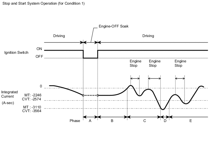
- Integrated Current Condition 1:
When a low battery temperature condition is not detected (the battery temperature is 11°C (51.8°F) or more) and battery charge condition is good:
-
Phase A:
When the ignition switch is turned off, the integrated current value is recorded in the ECU memory. The value is carried over to the next trip.
-
Phase B:
After engine start by ignition switch operation, Stop and Start system control is prohibited until the integrated current reaches 0 A-sec once. (The battery is being charged during this phase.)
-
Phase C:
Stop and Start system control is permitted until the integrated current decreases to -3110 A-sec. (for Manual transaxle)
Stop and Start system control is permitted until the integrated current decreases to -3564 A-sec. (for CVT)
-
Phase D:
After the integrated current value decreases below -3110 A-sec, Stop and Start system control is prohibited until the value increases to -2246 A-sec or more again. (The battery is being charged during this phase.) (for Manual transaxle)
After the integrated current value decreases below -3564 A-sec, Stop and Start system control is prohibited until the value increases to -2574 A-sec or more again. (The battery is being charged during this phase.) (for CVT)
-
Phase E:
Stop and Start system control is permitted. After this, system control is permitted until the integrated current decreases below -3110 A-sec. (for Manual transaxle)
Stop and Start system control is permitted. After this, system control is permitted until the integrated current decreases below -3564 A-sec. (for CVT)
Stop and Start System Operation (for Condition 1)
-
- Integrated Current Condition 2:
When a low battery temperature condition is detected (the battery temperature is less than 10°C (50°F)):
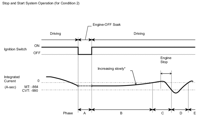
*: The integrated current increases slowly due to low battery charge acceptance at low temperature.
-
Phase A:
When the ignition switch is turned off, the integrated current value is recorded in the ECU memory. The value is carried over to the next trip.
-
Phase B:
After engine start by ignition switch operation, Stop and Start system control is prohibited until the integrated current reaches 0 A-sec once. (The battery is being charged during this phase.)
-
Phase C:
Stop and Start system control is permitted until the integrated current decreases to -864 A-sec. (for Manual transaxle)
Stop and Start system control is permitted until the integrated current decreases to -990 A-sec. (for CVT)
-
Phase D:
After the integrated current value decreases below -864 A-sec, Stop and Start system control is prohibited until the value increase to 0 A-sec or more again. (The battery is being charged during this phase.) (for Manual transaxle)
After the integrated current value decreases below -990 A-sec, Stop and Start system control is prohibited until the value increase to 0 A-sec or more again. (The battery is being charged during this phase.) (for CVT)
-
Phase E:
Stop and Start system control is permitted. If the battery temperature becomes 11°C (51.8°F) or higher and the battery charge condition meets a predetermined condition, Stop and Start system operation switches to Integrated Current Condition 1 above.
Stop and Start System Operation (for Condition 2)
-
Tech Tips
-
The low battery temperature condition is detected when the battery temperature is less than 10°C (50°F). When the battery temperature becomes 11°C (51.8°F) or more, the low battery temperature condition is cleared.
-
Performance (internal resistance) of lead-acid batteries used in typical vehicles changes according to the battery temperature. The internal resistance of the battery tends to be higher when the battery temperature is low. Thus, the Stop and Start system switches the threshold for determining the power charge according to the battery temperature when performing stop and start control.
-
If the battery is deteriorated, the internal resistance has also increased and the stop and start rate becomes lower. (The total of idling time while the vehicle is stopped increases.)
-
When troubleshooting, if the malfunction cannot be identified, the battery might be deteriorated.
-
-
ACTIVE TEST
Tech Tips
Using the intelligent tester to perform Active Tests allows relays, actuators and other items to be operated without removing any parts. This non-intrusive functional inspection can be very useful because intermittent operation may be discovered before parts or wiring is disturbed. Performing Active Tests early in troubleshooting is one way to save diagnostic time. Data List information can be displayed while performing Active Tests.
-
Connect the intelligent tester to the DLC3.
-
Start the engine.
-
Turn the tester on.
-
Enter the following menus: Powertrain / Stop and Start / Active Test.
-
Perform the Active Test by referring to the table below.
Stop and Start System Tester Display Test Part Control Range Diagnostic Note Buzzer Buzzer activation ON/OFF - Starter Starter activation ON/OFF Refer to DTC P1545 if the test is unavailable. Permit Cond (A/C) A/C ON/OFF - Permit Cond (Battery) Battery ON/OFF - Permit Cond (Engine) Engine ON/OFF - Permit Cond (ABS) ABS/VSC ON/OFF - AT Oil Pump (Hi) AT oil pump activation ON/OFF HI activation AT Oil Pump (Lo) AT oil pump activation ON/OFF LO activation Precondition (Control) Precondition (Control) activation ON/OFF Condition of permission or prohibition for terms listed below.
(ECM, battery, skid control ECU, idling (engine speed), ignition switch elapsed time, stop and start control system is normal, A/C system, starter circuit normal, engine hood close, driver door close, stop and start cancel switch, brake booster vacuum, power source, EPS system, starter, CVT system, brake control system, key operation, interval of time, initial driving)
Precondition2 (Control) Precondition2 (Control) activation ON/OFF Condition of permission or prohibition for terms listed below.
(Gradient of road surface, shift range, starter circuit malfunction.)
Start Cond (Hood Crtsy) Engine hood ON/OFF - Tech Tips
Even if Stop and Start system control is prohibited due to the condition of any of the systems listed above, performing the Active Tests allows Stop and Start system control to be performed.
-