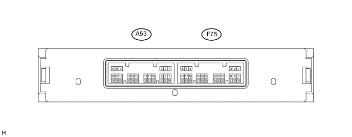
STOP AND START SYSTEM TERMINALS OF ECU
-
ENGINE STOP AND START ECU
-
Disconnect the A53 and F75 engine stop and start ECU connector.
-
Measure the resistance and voltage according to the value(s) in the table below.
Terminal No.
(Symbol)
Wiring Color Terminal Description Condition Specified Condition A53-1 (CA3N) - Body ground W - Body ground CAN communication Always 10 kΩ or higher A53-2 (CA3P) - Body ground B - Body ground CAN communication Always 10 kΩ or higher A53-10 (NE) - Body ground V - Body ground Crankshaft position sensor signal Always 10 kΩ or higher A53-11 (+B) - Body ground B - Body ground Power source of engine stop and start ECU Ignition switch ON 9.5 to 14 V A53-13 (AM21) - Body ground B - Body ground Battery Always 9.5 to 14 V A53-14 (LIN1) - Body ground Y - Body ground LIN communication signal Always 10 kΩ or higher F75-1 (CA1L) - Body ground W - Body ground CAN communication Always 10 kΩ or higher F75-2 (CA1H) - Body ground BE - Body ground CAN communication Always 10 kΩ or higher F75-5 (GND2) - Body ground BR - Body ground Ground Always Below 1 Ω F75-6 (GND1) - Body ground BR - Body ground Ground Always Below 1 Ω -
Reconnect the A53 and F75 engine stop and start ECU connector.
-
Measure the resistance, voltage and waveform according to the value(s) in the table below.
Terminal No.
(Symbol)
Wiring Color Terminal Description Condition Specified Condition A53-4 (STA) - F75-6 (GND) P - BR Starter operation signal Cranking 6 V or higher A53-5 (DDON) - F75-6 (GND) L - BR Backup boost converter signal Engine running Pulse generation
(see waveform 1)
A53-6 (CLL) - F75-6 (GND) R - W-B Clutch start switch (lower) signal*1 Ignition switch ON, clutch pedal released 8 to 14 V Ignition switch ON, clutch pedal fully depressed 0 to 1.5 V Park/Neutral position switch signal*2 Ignition switch ON, shift lever in P or N 8 to 14 V Ignition switch ON, shift lever in other than P or N 0 to 1.5 V A53-7 (OPM1) - F75-6 (GND) P - BR Oil pump motor output signal Ignition switch ON, engine stopped, activate the AT oil pump (Lo) Pulse generation
(see waveform 2)
A53-8 (OPM2) - F75-6 (GND) SB - BR Oil pump relay signal Ignition switch ON, engine stopped, activate the AT oil pump (Lo) 8 to 14 V A53-9 (OPST) - F75-6 (GND) V - BR Oil pump motor condition signal Idling after engine warmed up 8 to 14 V Ignition switch ON, engine stopped, activate the AT oil pump (Lo) Pulse generation
(see waveform 3)
A53-10 (NE) - F75-6 (GND) V - BR Engine speed signal from ECM Idling after engine warmed up Pulse generation
(see waveform 4)
A53-18 (BNT1) - F75-6 (GND) P - BR Engine hood courtesy switch signal Ignition switch ON, engine stopped, engine hood closed 0 to 1.5 V Ignition switch ON, engine stopped, engine hood open 8 to 14 V A53-19 (BRE2) - Body ground B - Body ground Body ground (Brake booster pressure sensor) Always Below 1 Ω A53-20 (PB) - A53-19 (BRE2) LG - B Brake booster pressure sensor signal Ignition switch ON, absolute pressure of 40 kPa (300 mmHg) applied to sensor 1.6 to 2.0 V Ignition switch ON, absolute pressure of 60 kPa (450 mmHg) applied to sensor 2.2 to 2.6 V Ignition switch ON, atmospheric pressure applied to vacuum sensor 3.4 to 3.8 V A53-21 (BRVC) - F75-6 (GND) G - BR Brake booster pressure sensor power supply Ignition switch ON, engine stopped 4.5 to 5.5 V A53-24 (E2) - Body ground V - Body ground Body ground (Battery current sensor) Always Below 1 Ω A53-25 (IB) - F75-6 (GND) L - BR Battery current sensor Ignition switch ON 0.2 to 4.8 V A53-26 (VC) - F75-6 (GND) P - BR Battery current sensor power supply Ignition switch ON, engine stopped 4.5 to 5.5 V A53-27 (THB) - F75-6 (GND) SB - BR Battery temperature sensor Ignition switch ON 0.2 to 4.8 V A53-29 (TMN) - F75-6 (GND) W - BR Neutral position switch signal Ignition switch ON, shift lever in neutral 2.7 to 4.3 V Ignition switch ON, shift lever in any position other than neutral 0.7 to 1.9 V F75-3 (CLU) - F75-6 (GND) B - W-B Clutch switch (upper) signal Clutch pedal released 8 to 14 V Clutch pedal depressed 0 to 1.5 V F75-4 (IG2) - F75-6 (GND) GR - BR Ignition switch signal Ignition switch off 1 V or less Ignition switch ON, engine stopped 8 to 14 V F75-18 (ECAN) - F75-6 (GND) SB - BR Stop and start cancel switch signal Ignition switch ON, stop and start cancel switch on 0 to 1.5 V Ignition switch ON, stop and start cancel switch off 8 to 14 V F75-23 (TFAL) - F75-6 (GND) Y - BR A/C cooler thermistor signal Ignition switch ON, A/C on with set temperature of 10 to 30°C (50 to 86°F) 2.4 to 2.9 V F75-29 (SBL) - F75-6 (GND) SB - W-B Blower switch signal Ignition switch ON, blower switch on 0 to 1.5 V Ignition switch ON, blower switch off 8 to 14 V -
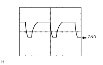
Waveform 1
Eco Run Vehicle Converter (Backup Boost Converter) Signal Item Content Tester connection DDON - GND Tool setting 5 V/DIV, 2 ms/DIV Vehicle condition Engine running Tech Tips
According to the state of the eco run vehicle converter assembly, each waveform changes.
-
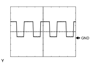
Waveform 2
Oil Pump Motor Output Signal Item Content Tester connection OPM1 - GND Tool setting 5 V/DIV, 5 ms/DIV Vehicle condition Engine stopped
(Stop and start system operation)
-
Waveform 3
Oil Pump Motor Condition Signal Item Content Tester connection OPST - GND Tool setting 5 V/DIV, 5 ms/DIV Vehicle condition Engine stopped
(Stop and start system operation)
-
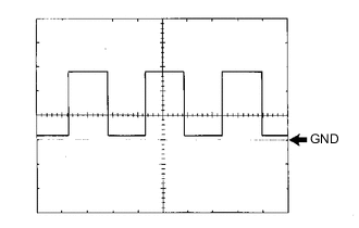
Waveform 4
Engine Speed Signal Item Content Tester connection NE - GND Tool setting 5 V/DIV, 2 ms/DIV Vehicle condition Idling after engine warmed up Tech Tips
The wavelength become shorter as the engine speed increases.
-