CRUISE CONTROL SYSTEM TERMINALS OF ECM
-
CHECK ECM
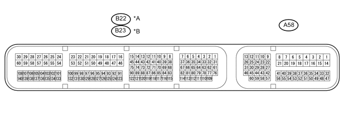
Text in Illustration *A for LHD *B for RHD
-
Measure the voltage and resistance according to the value(s) in the table below.
for LHD Terminal No. (Symbol) Wiring Color Terminal Description Condition Specified Condition A58-1 (BATT) - B22-16 (E1) Y - W-B Power source circuit Always 11 to 14 V A58-9 (STP) - B22-16 (E1) LG - W-B Stop light switch signal circuit Brake pedal depressed 11 to 14 V Brake pedal released Below 1 V A58-10 (ST1-) - B22-16 (E1) Y - W-B Stop light switch signal circuit Ignition switch ON, brake pedal released 11 to 14 V Ignition switch ON, brake pedal depressed Below 1 V B22-16 (E1) - Body ground W-B - Body ground Ground Always Below 1 Ω A58-37 (IGSW) - B22-16 (E1) R - W-B IG power source circuit Ignition switch ON 11 to 14 V Ignition switch off Below 1 V A58-41 (S) - B22-16 (E1)*1 V - W-B Park/neutral position switch signal Ignition switch ON, shift lever in D 11 to 14 V Ignition switch ON, shift lever not in D Below 1 V A58-41 (S) - B22-16 (E1)*2 V - W-B Clutch switch signal Ignition switch ON, clutch pedal depressed 11 to 14 V Ignition switch ON, clutch pedal released Below 1 V A58-60 (CCS) - B22-16 (E1) G - W-B Cruise control main switch circuit Cruise control main switch on Below 2.5 Ω Cruise control main switch off 1 MΩ or higher +RES switch held on 235 to 245 Ω -SET switch held on 617 to 643 Ω CANCEL switch held on 1509 to 1571 Ω
-
*1: for CVT
-
*2: for Manual Transaxle
for RHD Terminal No. (Symbol) Wiring Color Terminal Description Condition Specified Condition A58-1 (BATT) - B23-16 (E1) Y - W-B Power source circuit Always 11 to 14 V A58-9 (STP) - B23-16 (E1) LG - W-B Stop light switch signal circuit Brake pedal depressed 11 to 14 V Brake pedal released Below 1 V A58-10 (ST1-) - B23-16 (E1) Y - W-B Stop light switch signal circuit Ignition switch ON, brake pedal released 11 to 14 V Ignition switch ON, brake pedal depressed Below 1 V B23-16 (E1) - Body ground W-B - Body ground Ground Always Below 1 Ω A58-37 (IGSW) - B23-16 (E1) R - W-B IG power source circuit Ignition switch ON 11 to 14 V Ignition switch off Below 1 V A58-41 (S) - B23-16 (E1)*1 V - W-B Park/neutral position switch signal Ignition switch ON, shift lever in D 11 to 14 V Ignition switch ON, shift lever not in D Below 1 V A58-41 (S) - B23-16 (E1)*2 V - W-B Clutch switch signal Ignition switch ON, clutch pedal depressed 11 to 14 V Ignition switch ON, clutch pedal released Below 1 V A58-60 (CCS) - B23-16 (E1) G - W-B Cruise control main switch circuit Cruise control main switch on Below 2.5 Ω Cruise control main switch off 1 MΩ or higher +RES switch held on 235 to 245 Ω -SET switch held on 617 to 643 Ω CANCEL switch held on 1509 to 1571 Ω
-
*1: for CVT
-
*2: for Manual Transaxle
-
-