STARTER REASSEMBLY
PROCEDURE
-
INSTALL STARTER CLUTCH SUB-ASSEMBLY
-
Apply grease to the bushing and spline of the starter clutch and stop collar.
Text in Illustration 
High-temperature Grease -
Place the starter clutch and stop collar on the planetary shaft.
-
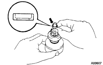
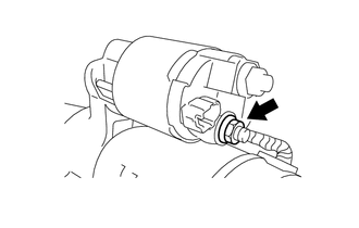
Apply high-temperature grease to a new snap ring, and install it onto the shock absorber groove.
-
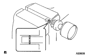
Using a vise, compress the snap ring.
-
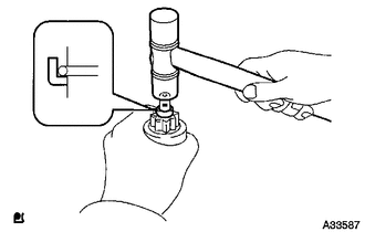
While holding the starter clutch sub-assembly, tap the shock absorber and install the stop collar onto the snap ring with a plastic-faced hammer.
-
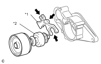
Text in Illustration *1 Starter Pinion Drive Lever *2 Starter Clutch Sub-assembly High-temperature Grease Apply high-temperature grease to the parts of the starter pinion drive lever that contact the pivot part of the starter housing.
-
Install the starter pinion drive lever onto the starter clutch sub-assembly.
-
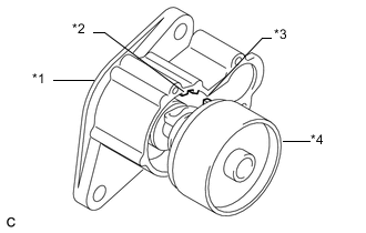
Text in Illustration *1 Starter Housing *2 Cutout *3 Protrusion *4 Shock Absorber Align the protrusion of the shock absorber with the cutout of the starter housing and install it.
-
-
INSTALL STARTER ARMATURE ASSEMBLY
-
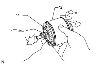
Text in Illustration *1 Starter Armature Assembly *2 Starter Yoke Assembly Install the starter armature assembly onto the starter yoke assembly.
-
-
INSTALL STARTER BRUSH HOLDER ASSEMBLY
-
Install the starter brush holder assembly.
-
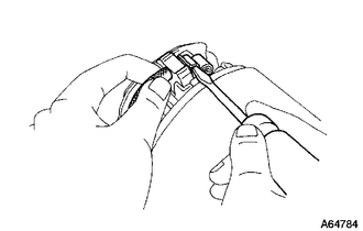
Using a screwdriver, hold the brush spring back, and install the 4 brushes into the brush holder.
-
Apply spindle oil to the bearing of the commutator end frame.
-
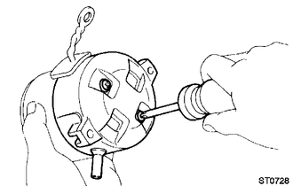
Install the commutator end frame with 2 new screws.
- Torque:
- 1.5 N*m { 15 kgf*cm, 13 in.*lbf }
Note
To avoid interference between the brush holder and the dust protector, push the commutator end frame away at an angle.
-
-
INSTALL STARTER YOKE ASSEMBLY
-
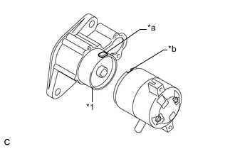
Text in Illustration *1 Shock Absorber *a Protrusion *b Cutout Align the cutout of the field frame with the protrusion of the shock absorber.
-
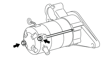
Install the field frame and the starter armature assembly with the 2 through bolts.
- Torque:
- 5.9 N*m { 60 kgf*cm, 52 in.*lbf }
-
-
INSTALL MAGNET STARTER SWITCH ASSEMBLY
-
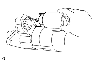
Hang the plunger hook of the magnet starter switch assembly in the starter pinion drive lever from the upper side.
-
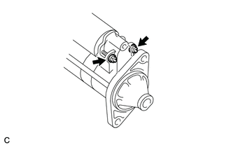
Install the magnet starter switch assembly with the 2 nuts.
- Torque:
- 8.3 N*m { 85 kgf*cm, 73 in.*lbf }
-
Connect the lead wire to the terminal with the nut.
- Torque:
- 9.8 N*m { 100 kgf*cm, 87 in.*lbf }
-