STARTER REASSEMBLY
PROCEDURE
-
INSTALL STARTER CENTER BEARING CLUTCH SUB-ASSEMBLY
-
Apply high-temperature grease to the bushing and spline of the starter center bearing clutch sub-assembly and pinion stop nut.
-
Place the starter center bearing clutch sub-assembly and pinion stop nut on the planetary carrier.
-
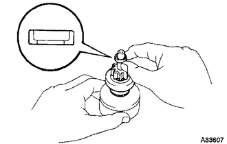
Apply high-temperature grease to a new snap ring, and install it onto the planetary carrier groove.
-
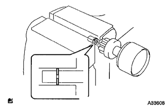
Using a vise, compress the snap ring.
-
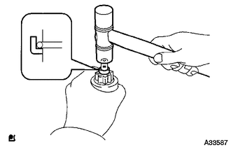
While holding the starter clutch sub-assembly, tap the planetary carrier and install the pinion stop nut onto the snap ring with a plastic-faced hammer.
-
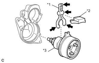
Text in Illustration *1 Pinion Drive Lever *2 Rubber Seal *3 Starter Center Bearing Clutch Sub-assembly 
High-temperature grease Apply high-temperature grease to the parts of the pinion drive lever that contact the starter pivot part of the pinion drive lever.
-
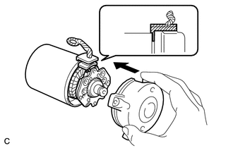
Install the pinion drive lever and rubber seal into the starter center bearing clutch sub-assembly.
-
Install the starter center bearing clutch together with the pinion drive lever into the starter drive housing assembly.
-
-
INSTALL PLANETARY GEAR
-
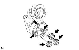
Apply high-temperature grease to the 3 planetary gears and pin parts of the planetary carrier.
Text in Illustration High-temperature grease -
Install the 3 planetary gears.
-
-
INSTALL STARTER ARMATURE ASSEMBLY
-
Install the starter armature assembly with the starter brush holder assembly onto the starter yoke assembly.
-
-
INSTALL STARTER BRUSH HOLDER ASSEMBLY
-
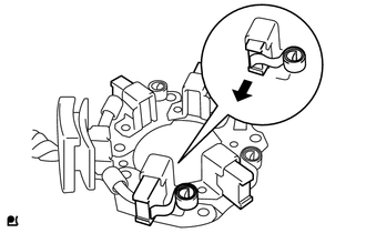
Using a screwdriver, hold the 4 brush springs back and install the 4 brushes into the starter brush holder assembly.
-
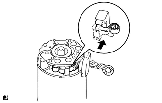
Install the starter brush holder assembly to the starter armature assembly.
-
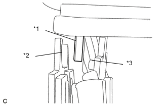
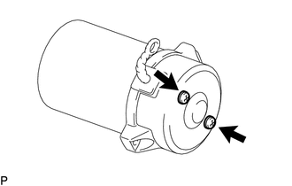
Text in Illustration *1 Grommet *2 Negative (-) Pole *3 Positive (+) Pole Insert the grommet between the positive (+) pole and negative (-) pole.
-
-
INSTALL STARTER COMMUTATOR END FRAME ASSEMBLY
-
Fit the clamp of the starter brush holder assembly into the starter commutator end frame assembly.
-
Install the starter commutator end frame assembly with the 2 screws.
- Torque:
- 1.5 N*m { 15 kgf*cm, 13 in.*lbf }
-
-
INSTALL STARTER ARMATURE PLATE
-
Install the starter armature plate onto the starter yoke assembly.
-
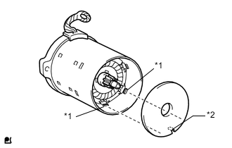
Text in Illustration *1 Key *2 Keyway Install the starter plate so that the keyway is positioned between the keys.
-
-
INSTALL STARTER COMMUTATOR END FRAME ASSEMBLY
-
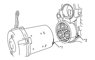
Text in Illustration *1 Key *2 Keyway Align the key of the starter yoke with the keyway located on the starter drive housing assembly.
-
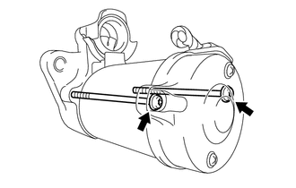
Install the starter drive housing assembly with the 2 through bolts.
- Torque:
- 6.0 N*m { 61 kgf*cm, 53 in.*lbf }
-
-
INSTALL MAGNET STARTER SWITCH ASSEMBLY
-
Apply high-temperature grease to the plunger hook.
-
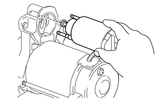
Hang the plunger of the magnet starter switch assembly into the pinion drive lever from the upper side.
-
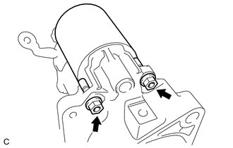
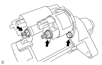
Install the magnet starter switch assembly with the 2 nuts.
- Torque:
- 7.5 N*m { 76 kgf*cm, 66 in.*lbf }
-
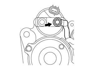
Connect the lead wire to the magnet starter switch, then fasten it with the nut.
- Torque:
- 9.0 N*m { 92 kgf*cm, 80 in.*lbf }
-
-
INSTALL STARTER INRUSH CURRENT REDUCTION RELAY
-
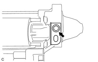
Install the starter inrush current reduction relay with the bolt.
- Torque:
- 7.9 N*m { 81 kgf*cm, 70 in.*lbf }
-
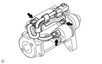
Connect the lead wire with the 2 nuts.
- Torque:
- 9.0 N*m { 92 kgf*cm, 80 in.*lbf }
-
-
INSTALL WIRE HARNESS
-
Install the wire harness with the bolt.
- Torque:
- 7.9 N*m { 81 kgf*cm, 70 in.*lbf }
-
Connect the 2 connectors.
-
-
INSTALL HARNESS BRACKET
-
Install the harness bracket with the bolt.
- Torque:
- 6.0 N*m { 61 kgf*cm, 53 in.*lbf }
-