STARTER INSPECTION
PROCEDURE
-
INSPECT STARTER ASSEMBLY
CAUTION:
As a large electric current passes through the cable during this inspection, a thick cable must be used. If not, the cable may became hot and cause injury.
Note
Perform each of the following tests within 3 to 5 seconds.
-
Perform pull-in test.
-
Disconnect the field coil lead wire from terminal C.
-
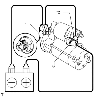
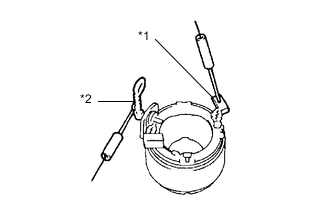
Text in Illustration *1 Starter Housing *2 Terminal C *3 Terminal 50 Connect the battery to the starter magnetic switch as shown in the illustration and check that the pinion gear is extended.
If the pinion gear does not move, replace the magnet starter switch assembly.
-
-
Perform holding test.
-
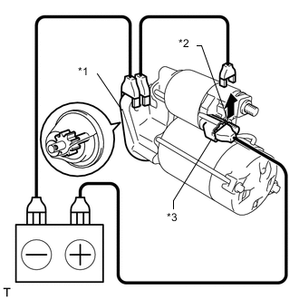
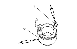
Text in Illustration *1 Starter Housing *2 Terminal C *3 Terminal 50 Check that the pinion gear does not return inward after the cable of terminal C is disconnected.
If the pinion gear returns inward, replace the magnet starter switch assembly.
-
-
Inspect the clutch pinion gear return.
-
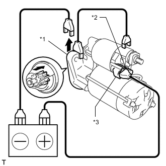
Text in Illustration *1 Starter Housing *2 Terminal C *3 Terminal 50 Disconnect the negative (-) lead from the starter housing and move the pinion gear toward the armature.
If the pinion gear does not return inward, replace the magnet starter switch assembly.
-
-
Perform the operation test without load.
-
Connect the field coil lead wire to terminal C.
- Torque:
- 9.8 N*m { 100 kgf*cm, 87 in.*lbf }
-
Clamp the starter in a vise.
-
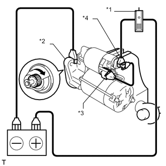
Text in Illustration *1 Ammeter *2 Starter Housing *3 Terminal 50 *4 Terminal 30 Connect the battery and ammeter to the starter as shown in the illustration.
-
Check that the ammeter indicates the specified current.
Tester Connection Condition Specified Condition Battery positive terminal - Terminal 30 - Terminal 50 11.5 V Below 90 A If the result is not as specified, replace the starter assembly.
-
-
-
INSPECT STARTER ARMATURE ASSEMBLY
-
Check the commutator for open circuits.
-
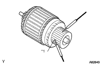
Text in Illustration *1 Segment to Segment Using an ohmmeter, check the resistance between the segments of the commutator.
Standard resistance Below 1 Ω If the result is not as specified, replace the starter armature assembly.
-
-
Check the commutator for ground.
-
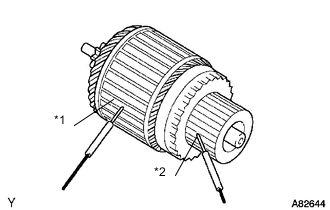
Text in Illustration *1 Armature core *2 Commutator Using an ohmmeter, check the resistance between the commutator and the armature core.
Standard resistance 10 kΩ or higher If the result is not as specified, replace the starter armature assembly.
-
-
Check the commutator surface for dirt and burns.
If the surface is dirty or burnt, restore it with sandpaper (No. 400) or a lathe.
-
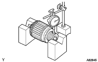
Check for the commutator cirumference runout.
-
Place the commutator on V-blocks.
-
Using a dial indicator, measure the cirumference runout.
Maximum runout 0.05 mm (0.00197 in.) If the runout is greater than the maximum, replace the starter armature assembly.
-
-
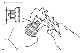
Using a vernier caliper, measure the commutator diameter.
Standard diameter 28.0 mm (1.1024 in.) Minimum diameter 27.0 mm (1.0630 in.) If the diameter is less than the minimum, replace the starter armature assembly.
-
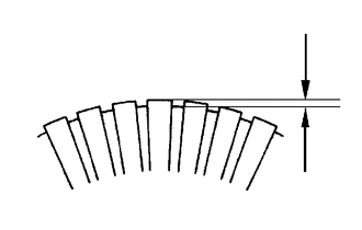
Check that the undercut portion between the segments is free of foreign matter and measure its depth.
Standard undercut depth 0.6 mm (0.0236 in.) Minimum undercut depth 0.2 mm (0.0079 in.) If the undercut depth is less than the minimum, adjust it with a hacksaw blade.
-
-
INSPECT STARTER YOKE ASSEMBLY
-
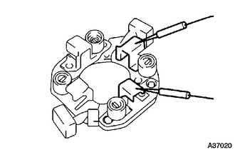
Text in Illustration *1 Brush *2 Terminal C Using an ohmmeter, check the resistance between terminal C and the field coil brush lead.
Standard resistance Below 1 Ω If the result is not as specified, replace the starter yoke assembly.
-
Text in Illustration *1 Brush *2 Starter Yoke Assembly Using an ohmmeter, check the resistance between the brush lead and the starter yoke assembly.
Standard resistance 10 kΩ or higher If the result is not as specified, replace the starter yoke assembly.
-
-
INSPECT BRUSH
-
Using a vernier caliper, measure the brush length.
Standard length 14 mm (0.5511 in.) Minimum length 9 mm (0.3543 in.) If the length is less than the minimum, replace the starter brush holder assembly and the starter yoke assembly.
-
-
INSPECT STARTER BRUSH HOLDER ASSEMBLY
-
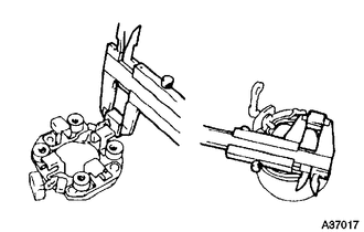
Using an ohmmeter, measure the resistance between the positive (+) and negative (-) brush holders.
Standard resistance 10 kΩ or higher If the result is not as specified, replace the starter brush holder assembly.
-
-
INSPECT STARTER CLUTCH SUB-ASSEMBLY
-
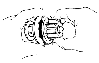
Text in Illustration *a Free *b Lock Hold the starter clutch and rotate the pinion gear clockwise, and check that it turns freely. Try to rotate the pinion gear counterclockwise and check that it locks.
If necessary, replace the starter clutch sub-assembly.
-
-
INSPECT MAGNET STARTER SWITCH ASSEMBLY
-
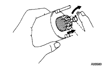
Check the plunger.
-
Push in the plunger and check that it returns quickly to its original position.
Note
To avoid damaging the inside of the magnet starter switch, do not release the plunger quickly.
-
-
Inspect the pull-in coil.
-
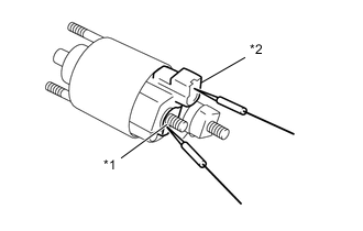
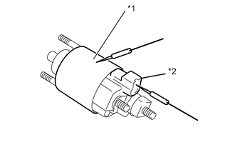
Text in Illustration *1 Terminal C *2 Terminal 50 Using an ohmmeter, check the resistance between terminals 50 and C.
Standard resistance Below 1 Ω If the result is not as specified, replace the magnet starter switch assembly.
-
-
Inspect the holding coil.
-
Text in Illustration *1 Switch Body *2 Terminal 50 Using an ohmmeter, check the resistance between terminal 50 and the switch body.
Standard resistance Below 2 Ω If the result is not as specified, replace the magnet starter switch assembly.
-
-