STARTER(w/ Stop And Start System) REASSEMBLY
PROCEDURE
-
INSTALL STARTER CENTER BEARING CLUTCH SUB-ASSEMBLY
-
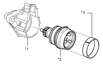
Text in Illustration *1 Starter Drive Housing Assembly *2 Starter Center Bearing Clutch Sub-assembly *3 Collar Space Install the starter center bearing clutch sub-assembly into the starter drive housing assembly.
-
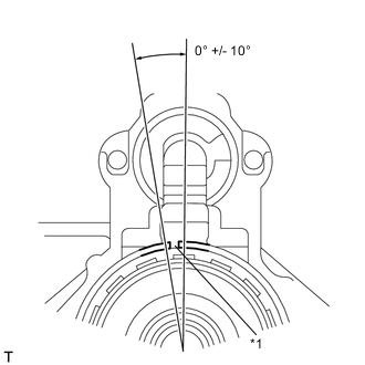
Text in Illustration *1 Collar Space End Gap Install the collar space into the starter center bearing clutch sub-assembly.
Note
Make sure that the collar space end gap rests within +/- 10° from the center of the starter drive housing assembly.
-
-
INSTALL PLANETARY GEAR AND WASHER
-
Text in Illustration 
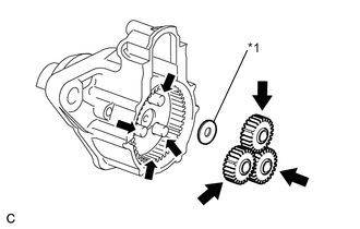
High-temperature Grease *1 Washer Apply high-temperature grease to the planetary gears and pin parts of the planetary shaft as shown in the illustration.
-
Install the washer and 3 planetary gears.
-
-
INSTALL STARTER YOKE ASSEMBLY
-
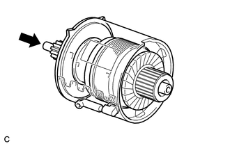
Install the starter yoke assembly onto the starter with clutch armature assembly.
Note
When installing the starter yoke assembly, be sure to hold the front of the armature to prevent the armature from coming off the clutch.
-
-
INSTALL STARTER BRUSH HOLDER ASSEMBLY
-
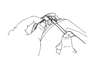
Using a screwdriver, hold the brush springs back and install the 4 brushes into the brush holder.
-
Install the brush holder to the starter armature.
-
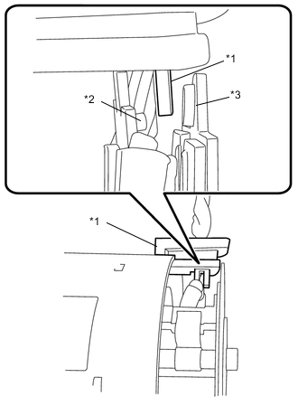
Text in Illustration *1 Grommet *2 Ground Plate (Negative Side) *3 Plate (Positive Side) Insert the grommet between the plate (positive side) and ground plate (negative side).
Note
Make sure that the grommet is properly inserted into the starter yoke assembly.
-
-
INSTALL STARTER COMMUTATOR END FRAME ASSEMBLY
-
Fit the clamp of the brush holder into the starter commutator end frame assembly.
-
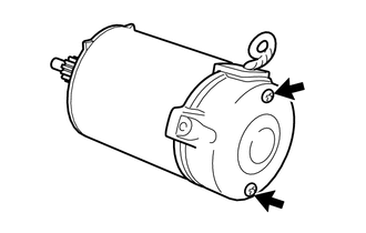
Install the starter commutator end frame with the 2 screws.
- Torque:
- 1.5 N*m { 15 kgf*cm, 13 in.*lbf }
-
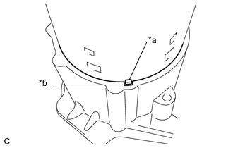
Text in Illustration *a Projection *b Cutout Install the starter yoke assembly, starter with clutch armature assembly and end frame with the starter drive housing assembly.
Note
Align the projection on the starter yoke assembly with the cutout on the starter drive housing assembly.
-
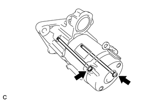
Using "TORX" socket wrench T25, install the starter yoke assembly with the 2 through bolts.
- Torque:
- 5.5 N*m { 56 kgf*cm, 49 in.*lbf }
-
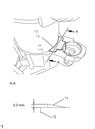
Text in Illustration *1 Rubber Seal *2 Starter Drive Housing Install rubber seal to the starter drive housing assembly.
Note
Make sure that the rubber seal does not protrude more than 2.0 mm (0.0787 in.) from the outer surface of the starter drive housing assembly.
-
-
INSTALL REPAIR SERVICE STARTER KIT
-
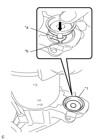
Text in Illustration *1 Cover *a Projection *b Cutout Install the cover by aligning the projection on the cover with the cutout on the housing.
Note
Make sure that the cover does not overlap the rubber seal.
-
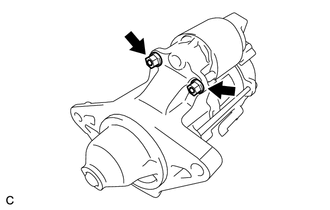
Install the repair service starter kit with the 2 nuts.
- Torque:
- 7.5 N*m { 76 kgf*cm, 66 in.*lbf }
-
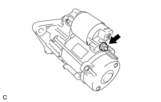
Connect the lead wire to terminal C with the nut.
- Torque:
- 10 N*m { 102 kgf*cm, 7 ft.*lbf }
-