OIL PUMP INSTALLATION

PROCEDURE
-
INSTALL OIL PUMP ASSEMBLY
-
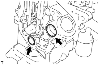
Install 2 new O-rings onto the 2 locations as shown in the illustration.
-
Apply seal packing to the oil pump assembly, cylinder head and cylinder block as shown in the illustration.
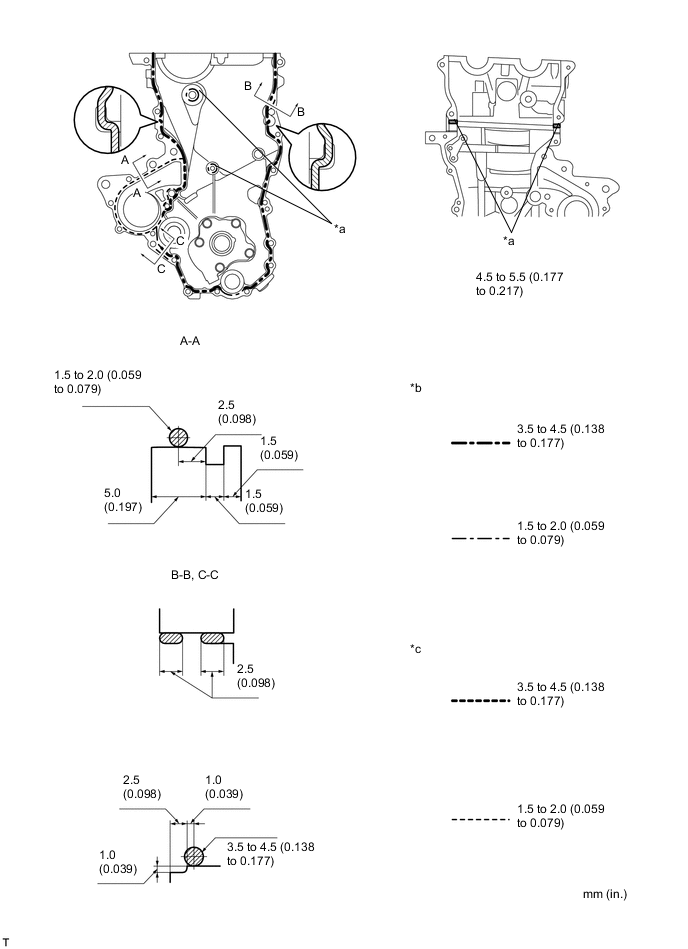
Text in Illustration *a Seal Packing *b Seal Width (Other Part) *c Seal Width (Water Pump Part) - - Seal packing Water pump part Toyota Genuine Seal Packing 1282B, Three Bond 1282B or equivalent Other part Toyota Genuine Seal Packing Black, Three Bond 1207B or equivalent Note
-
Remove any oil from the contact surfaces.
-
Install the oil pump assembly within 3 minutes and tighten the bolts and nut within 15 minutes of applying seal packing.
-
Do not expose the seal to engine oil for at least 2 hours after the installation.
-
-
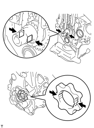
Align the keyway of the oil pump rotor with the rectangular portion of the crankshaft, and slide the oil pump into place.
-
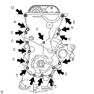
Install the oil pump assembly with the 15 bolts and the nut. Tighten the bolts and nut uniformly in several steps.
- Torque:
- bolt A
- 32 N*m { 326 kgf*cm, 24 ft.*lbf }
- bolt B
- 11 N*m { 112 kgf*cm, 8 ft.*lbf }
- bolt C
- 11 N*m { 112 kgf*cm, 8 ft.*lbf }
- nut D
- 24 N*m { 245 kgf*cm, 18 ft.*lbf }
- bolt E
- 24 N*m { 245 kgf*cm, 18 ft.*lbf }
Note
After installing the oil pump assembly, install the mounting bracket and water pump within 15 minutes.
Tech Tips
Each bolt length is as follows.
A: 30 mm (1.181 in.)
B: 35 mm (1.378 in.)
C: 20 mm (0.787 in.)
E: 14 to 20 mm (0.551 to 0.787 in.), Double ended bolt
-
-
INSTALL TRANSVERSE ENGINE ENGINE MOUNTING BRACKET
-
Install the transverse engine engine mounting bracket with the 4 bolts.
- Torque:
- 55 N*m { 561 kgf*cm, 41 ft.*lbf }
-
-
INSTALL WATER PUMP ASSEMBLY
-
INSTALL WATER PUMP PULLEY
-
INSTALL CAMSHAFT TIMING OIL CONTROL VALVE ASSEMBLY
-
INSTALL CRANKSHAFT POSITION SENSOR
-
INSTALL CRANKSHAFT DAMPER SUB-ASSEMBLY
-
Align the pin hole of the crankshaft damper with the pin and install the crankshaft damper sub-assembly.
-
Provisionally install the bolt.
-
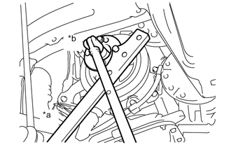
Text in Illustration *a Hold *b Tighten Using 2 SST, tighten the bolt while holding the crankshaft damper sub-assembly.
- SST
- 09213-14010 ( 91651-60865 )
- 09330-00021
- Torque:
- 128 N*m { 1305 kgf*cm, 95 ft.*lbf }
Note
Check the SST installation positions when installing them, to avoid the SST fixing bolts from coming into contact with the oil pump assembly.
-
-
INSTALL ENGINE MOUNTING INSULATOR SUB-ASSEMBLY RH
-
Install the engine mounting insulator sub-assembly RH with the 4 bolts and 2 nuts.
- Torque:
- 52 N*m { 530 kgf*cm, 38 ft.*lbf }
-
-
INSTALL CYLINDER HEAD COVER SUB-ASSEMBLY
-
INSTALL NO. 2 VENTILATION HOSE
-
INSTALL VENTILATION HOSE
-
INSTALL NO. 1 IGNITION COIL
-
INSTALL GENERATOR ASSEMBLY
-
INSTALL FAN AND GENERATOR V BELT
-
ADJUST FAN AND GENERATOR V BELT
-
INSPECT FAN AND GENERATOR V BELT
-
CONNECT CABLE TO NEGATIVE BATTERY TERMINAL
- Torque:
- 5.4 N*m { 55 kgf*cm, 48 in.*lbf }
-
ADD ENGINE OIL
-
ADD COOLANT
-
INSPECT ENGINE OIL LEVEL
-
INSPECT FOR OIL LEAK
-
INSPECT FOR COOLANT LEAK
-
INSTALL ENGINE UNDER COVER RH
-
INSTALL FRONT WHEEL RH
- Torque:
- 103 N*m { 1050 kgf*cm, 76 ft.*lbf }