OIL PUMP REMOVAL

PROCEDURE
-
DISCONNECT CABLE FROM NEGATIVE BATTERY TERMINAL
-
REMOVE FRONT WHEEL RH
-
REMOVE ENGINE UNDER COVER RH
-
DRAIN ENGINE OIL
-
DRAIN COOLANT
-
REMOVE FAN & GENERATOR V BELT
-
REMOVE GENERATOR ASSEMBLY
-
REMOVE GENERATOR BRACKET
-
REMOVE NO. 1 IGNITION COIL
-
DISCONNECT VENTILATION HOSE
-
DISCONNECT FUEL VAPOR FEED HOSE ASSEMBLY
-
REMOVE CYLINDER HEAD COVER SUB-ASSEMBLY
-
REMOVE ENGINE MOUNTING INSULATOR SUB-ASSEMBLY RH
-
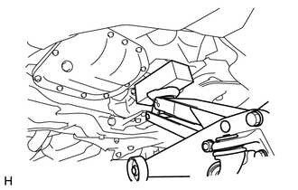
Place a plate lift attachment on a jack underneath the engine.
Note
-
To prevent deformation of the No. 2 oil pan sub-assembly, never set plate lift attachment against the No. 2 oil pan sub-assembly of the engine assembly with transaxle.
-
To prevent deformation of the transaxle oil pan sub-assembly, never set plate lift attachment against the transaxle oil pan sub-assembly of the continuously variable transaxle.
-
-
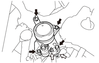
Remove the 4 bolts and 2 nuts and remove the engine mounting insulator sub-assembly RH.
Text in Illustration 
Bolt 
Nut
-
-
REMOVE CRANKSHAFT DAMPER SUB-ASSEMBLY
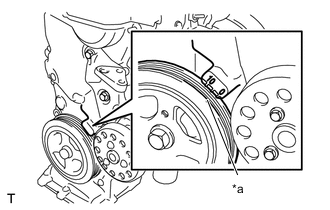
Text in Illustration *a Timing Notch
-
Set the No. 1 cylinder to TDC/compression.
-
Turn the crankshaft damper sub-assembly, and align its timing notch with timing mark "0" of the oil pump.
-
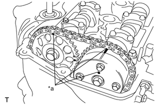
Text in Illustration *a Timing Marks Check that the timing marks on the camshaft timing sprocket and the camshaft timing gear are all facing upward as shown in the illustration.
If not, turn the crankshaft 1 complete revolution (360°) and align the marks as above.
-
-
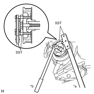
Text in Illustration *a Hold *b Loosen Using 2 SSTs, loosen the bolt while holding the crankshaft damper sub-assembly.
- SST
- 09213-14010 ( 91651-60865 )
- 09330-00021
Note
-
Check the SST installation positions when installing them, to avoid the SST fixing bolts from coming into contact with the oil pump assembly.
-
Be careful not let SST slip during the work.
-
Remove the SSTs and the bolt.
-
Remove the crankshaft damper sub-assembly.
-
-
REMOVE CRANK POSITION SENSOR
-
REMOVE CAMSHAFT TIMING OIL CONTROL VALVE ASSEMBLY
-
REMOVE V-RIBBED BELT TENSIONER ASSEMBLY
-
REMOVE WATER PUMP PULLEY
-
REMOVE ENGINE WATER PUMP ASSEMBLY
-
REMOVE TRANSVERSE ENGINE ENGINE MOUNTING BRACKET
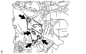
-
Remove the 4 bolts and remove the transverse engine engine mounting bracket.
-
-
REMOVE OIL PUMP ASSEMBLY
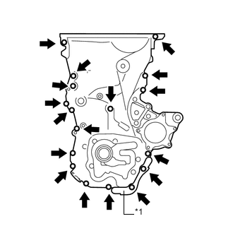
-
Remove the 16 bolts, nut and wire harness bracket.
Text in Illustration *1 Wire Harness Bracket -
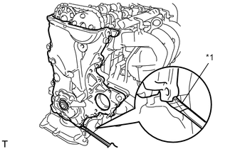
Text in Illustration *1 Protective Tape Using a screwdriver with its tip wrapped in protective tape, prize the oil pump assembly to remove it.
Note
Do not damage the contact surfaces of the oil pump assembly and oil pan sub-assembly.
-
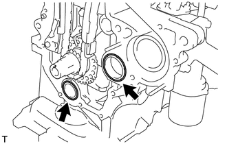
Remove the 2 O-rings from the cylinder block and oil pan sub-assembly.
-