COOLING FAN SYSTEM Cooling Fan Circuit
TECHNICAL DESCRIPTION
To control the cooling fans, the ECM turns on or off the cooling fan relays based on the engine coolant temperature, air conditioning switch, refrigerant pressure, engine speed and vehicle speed signals.
The ECM turns on or off the fan relays to switch the cooling fan motor circuit between the series circuit and parallel circuit, controlling the cooling fan motor speed in 2 steps.
WIRING DIAGRAM
Refer to System Diagram Click here.
CAUTION / NOTICE / HINT
Note
Inspect the fuses for circuits related to this system before performing the following inspection procedure.
PROCEDURE
-
CHECK FAN NO. 1 RELAY
-
Remove the FAN No. 1 relay from the engine room main relay block.
-
Measure the voltage according to the value(s) in the table below.
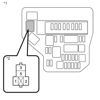
Standard Voltage Tester Connection Condition Specified Condition FAN No. 1 relay terminal 3 - Body ground Always 11 to 14V Text in Illustration *1 Engine Room Main Relay Block *2 FAN No. 1 Relay -
Reinstall the FAN No. 1 relay.
NG 
REPAIR OR REPLACE HARNESS AND CONNECTOR
OK 
-
-
CHECK ENGINE ROOM MAIN RELAY BLOCK
-
Remove the FAN No. 1 relay and FAN No. 2 relay from the engine room main relay block.
-
Turn the Ignition switch to ON.
-
Measure the voltage according to the value(s) in the table below.
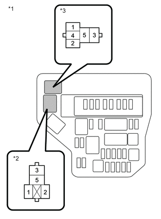
Standard Voltage Tester Connection Condition Specified Condition FAN No. 1 relay terminal 1 - Body ground Ignition switch ON 11 to 14V FAN No. 2 relay terminal 2 - Body ground Ignition switch ON 11 to 14V Text in Illustration *1 Engine Room Main Relay Block *2 FAN No. 1 Relay *3 FAN No. 2 Relay -
Reinstall the FAN No. 1 relay and FAN No. 2 relay.
NG
REPAIR OR REPLACE HARNESS AND CONNECTOR
OK
-
-
INSPECT FAN NO. 1 RELAY
-
Inspect the FAN No. 1 relay Click here.
NG
REPLACE FAN NO. 1 RELAY
OK
-
-
INSPECT FAN NO. 2 RELAY
-
Inspect the FAN No. 2 relay Click here.
NG
REPLACE FAN NO. 2 RELAY
OK
-
-
INSPECT COOLING FAN RESISTOR
-
Inspect the cooling fan resistor Click here.
NG
REPLACE COOLING FAN RESISTOR
OK
-
-
CHECK WIRE HARNESS AND CONNECTOR (FAN NO. 2 RELAY - BODY GROUND)
-
Remove the FAN No. 2 relay from the engine room main relay block.
-
Measure the resistance according to the value(s) in the table below.
Standard Resistance Tester Connection Condition Specified Condition FAN No. 2 relay terminal 5 - Body ground Always Below 1 Ω -
Reinstall the FAN No. 2 relay.
NG
REPAIR OR REPLACE HARNESS AND CONNECTOR
OK
-
-
CHECK WIRE HARNESS AND CONNECTOR (COOLING FAN RESISTOR - BODY GROUND)
-
Disconnect the cooling fan resistor connector.
-
Measure the resistance according to the value(s) in the table below.
Standard Resistance Tester Connection Condition Specified Condition A22-1 (-) - Body ground Always Below 1 Ω -
Connect the cooling fan resistor connector.
NG
REPAIR OR REPLACE HARNESS AND CONNECTOR
OK
-
-
CHECK WIRE HARNESS AND CONNECTOR (FAN NO. 2 RELAY - COOLING FAN RESISTOR)
-
Disconnect the cooling fan resistor connector.
-
Remove the FAN No. 2 relay from the engine room main relay block.
-
Measure the resistance according to the value(s) in the table below.
Standard Resistance (Check for Open) Tester Connection Condition Specified Condition FAN No. 2 relay terminal 4 - A22-2 (+) Always Below 1 Ω Standard Resistance (Check for Short) Tester Connection Condition Specified Condition A22-2 (+) or FAN No. 2 relay terminal 4 - Body ground Always 10 kΩ or higher -
Reinstall the FAN No. 2 relay.
-
Reconnect the cooling fan resistor connector.
NG
REPAIR OR REPLACE HARNESS AND CONNECTOR
OK
-
-
CHECK COOLING FAN MOTOR
-
Inspect the cooling fan motor Click here.
NG
REPLACE COOLING FAN MOTOR Click here
OK
-
-
CHECK WIRE HARNESS AND CONNECTOR (COOLING FAN MOTOR - FAN NO. 1 RELAY)
-
Disconnect the cooling fan motor connector.
-
Remove the FAN No. 1relay from the engine room main relay block.
-
Measure the resistance according to the value(s) in the table below.
Standard Resistance (Check for Open) Tester Connection Condition Specified Condition A21-2 - FAN No. 1 relay terminal 5 Always Below 1 Ω Standard Resistance (Check for Short) Tester Connection Condition Specified Condition A21-2 or FAN No. 1 relay terminal 5 - Body ground Always 10 kΩ or higher -
Reinstall the FAN No. 1 relay.
-
Reconnect the cooling fan motor connector.
NG
REPAIR OR REPLACE HARNESS AND CONNECTOR
OK
-
-
CHECK WIRE HARNESS AND CONNECTOR (COOLING FAN MOTOR - FAN NO. 2 RELAY)
-
Disconnect the cooling fan motor connector.
-
Remove the FAN No. 2 relay from the engine room main relay block.
-
Measure the resistance according to the value(s) in the table below.
Standard Resistance (Check for Open) Tester Connection Condition Specified Condition A21-1 - FAN No. 2 relay terminal 3 Always Below 1 Ω Standard Resistance (Check for Short) Tester Connection Condition Specified Condition A21-1 or FAN No. 2 relay terminal 3 - Body ground Always 10 kΩ or higher -
Reinstall the FAN No. 2 relay.
-
Reconnect the cooling fan motor connector.
NG
REPAIR OR REPLACE HARNESS AND CONNECTOR
OK
-
-
CHECK WIRE HARNESS AND CONNECTOR (ENGINE ROOM MAIN RELAY BLOCK - ECM)
-
Remove the FAN No. 1 relay and FAN No. 2 relay from the engine room main relay block.
-
Disconnect the ECM connector.
-
Measure the resistance according to the value(s) in the table below.
Standard Resistance (Check for Open) Tester Connection Condition Specified Condition A58-8 (FANH) - FAN No. 2 relay terminal 1 Always Below 1 Ω A58-7 (FANL) - FAN No. 1 relay terminal 2 Always Below 1 Ω Standard Resistance (Check for Short) Tester Connection Condition Specified Condition A58-8 (FANH) or FAN No. 2 relay terminal 1 - Body ground Always 10 kΩ or higher A58-7 (FANL) or FAN No. 1 relay terminal 2 - Body ground Always 10 kΩ or higher -
Reconnect the ECM connector.
-
Reinstall the FAN No. 1 relay and FAN No. 2 relay.
OK
REPLACE ECM Click here
NG
REPAIR OR REPLACE HARNESS AND CONNECTOR
-