INTAKE MANIFOLD INSTALLATION
PROCEDURE
-
INSTALL NO. 2 INTAKE MANIFOLD INSULATOR
-
Install the No. 2 intake manifold insulator to the cylinder block sub-assembly.
Tech Tips
Securely fit the end of the No. 2 intake manifold insulator under the engine oil level dipstick guide installation tab.
-
-
INSTALL NO. 1 INTAKE MANIFOLD TO HEAD GASKET
-
Install a new No. 1 intake manifold to head gasket to the intake manifold.
-
-
INSTALL INTAKE MANIFOLD
-
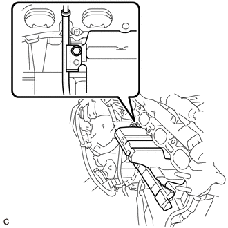
Install the plug to the intake manifold.
-
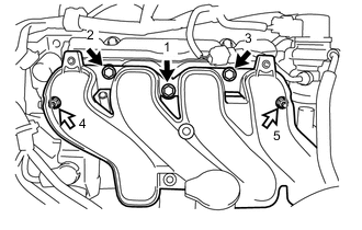
Temporarily install the intake manifold onto the cylinder head sub-assembly with the 3 bolts and 2 nuts.
Text in Illustration 
Bolt 
Nut -
Tighten the 3 bolts and 2 nuts in the order shown in the illustration.
- Torque:
- 30 N*m { 306 kgf*cm, 22 ft.*lbf }
-
Install the clamp to the generator assembly with the bolt.
- Torque:
- 4.6 N*m { 47 kgf*cm, 41 in.*lbf }
-
Engage the wire harness clamp and install the engine wire.
-
Install the oil level dipstick sub-assembly.
-
Engage the wire harness clamp and install the wire harness to the intake manifold.
-
Install the wire harness bracket with the bolt.
- Torque:
- 11 N*m { 112 kgf*cm, 8 ft.*lbf }
-
Engage the wire harness clamp to the wire harness bracket.
-
-
CONNECT UNION TO CONNECTOR TUBE HOSE
-
Connect the union to connector tube hose to the intake manifold.
-
-
CONNECT VENTILATION HOSE
-
Connect the ventilation hose to the intake manifold.
-
-
INSTALL STUD BOLT
-
Using an E6 "TORX" socket wrench, install the 3 stud bolts to the intake manifold.
- Torque:
- 4.0 N*m { 41 kgf*cm, 35 in.*lbf }
-
-
INSTALL THROTTLE BODY ASSEMBLY