EXHAUST MANIFOLD W/ TURBOCHARGER INSTALLATION
PROCEDURE
-
INSTALL EXHAUST MANIFOLD
-
Install a new gasket to the cylinder head.
-
Install the exhaust manifold with the 8 nuts.
- Torque:
- 43 N*m { 438 kgf*cm, 32 ft.*lbf }
-
-
INSTALL INLET COMPRESSOR ELBOW SUB-ASSEMBLY
-
Install a new gasket onto the inlet compressor elbow sub-assembly.
-
Install the inlet compressor elbow sub-assembly with the 3 nuts.
- Torque:
- 9.0 N*m { 92 kgf*cm, 80 in.*lbf }
-
-
TEMPORARILY INSTALL INLET TURBO OIL PIPE SUB-ASSEMBLY
-
Install a new gasket onto the cylinder block.
-
Temporarily install the inlet turbo oil pipe sub-assembly with the 2 nuts.
-
-
INSTALL TURBOCHARGER SUB-ASSEMBLY
-
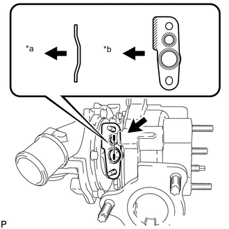
Text in Illustration *a Turbocharger side *b Compressor side Install a new gasket onto the turbocharger sub-assembly.
-
Install a new gasket onto the exhaust manifold.
-
Install the turbocharger sub-assembly with the 3 nuts.
- Torque:
- 53 N*m { 540 kgf*cm, 39 ft.*lbf }
-
Temporarily install the turbocharger stay with the 2 bolts and nut.
-
Tighten the 2 bolts.
- Torque:
- 37 N*m { 377 kgf*cm, 27 ft.*lbf }
-
Tighten the nut.
- Torque:
- 37 N*m { 377 kgf*cm, 27 ft.*lbf }
-
Install the manifold stay with the 2 bolts.
- Torque:
- 37 N*m { 377 kgf*cm, 27 ft.*lbf }
-
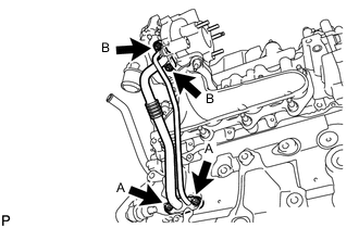
Tighten the 2 nuts B.
- Torque:
- 11 N*m { 112 kgf*cm, 8 ft.*lbf }
-
Tighten the 2 nuts A to install the inlet turbo oil pipe sub-assembly.
- Torque:
- 10 N*m { 102 kgf*cm, 7 ft.*lbf }
-
-
INSTALL NO. 1 AIR HOSE
-
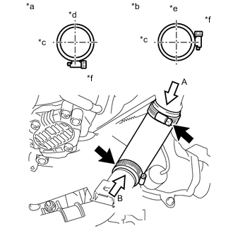
Text in Illustration *a View A *b View B *c Front Side *d RH Side *e Upper Side *f Clamp installation range Install the No. 1 air hose with the 2 hose clamps.
- Torque:
- 6.0 N*m { 61 kgf*cm, 53 in.*lbf }
-
-
INSTALL BATTERY CARRIER
-
INSTALL BATTERY TRAY
-
INSTALL BATTERY
-
INSTALL AIR CLEANER CASE SUB-ASSEMBLY
-
INSTALL AIR CLEANER FILTER ELEMENT SUB-ASSEMBLY
-
INSTALL AIR CLEANER CAP SUB-ASSEMBLY WITH HOSE
-
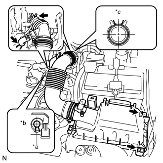
Text in Illustration *a Front Side *b RH Side *c Upper Side Connect the No. 1 air cleaner hose to the turbocharger sub-assembly and install the air cleaner hose clamp.
-
Connect the ventilation hose to the cylinder head cover.
-
Install the air cleaner cap onto the air cleaner case, then hang the 2 lock clamps.
-
Engage the 4 wire harness clamps.
-
Connect the mass air flow meter connector.
-
-
INSTALL EXHAUST MANIFOLD CONVERTER SUB-ASSEMBLY
-
CLEAR DTC (P0046)
-
When a new turbocharger is installed, DTC P0046 is likely to occur. It should be cleared by the special method Click here.
-