FUEL TANK INSTALLATION
PROCEDURE
-
INSTALL NO. 2 FUEL TANK FILLER PIPE SUPPORT
-
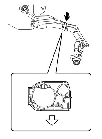
Engage the clamp and install the No. 2 fuel tank filler pipe support as shown in the illustration.
Text in Illustration 
Front of Vehicle
-
-
INSTALL NO. 1 FUEL TANK FILLER PIPE SUPPORT
-
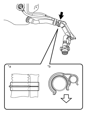
Text in Illustration *a Clamp Position *b Section Front of Vehicle Install the No. 1 fuel tank filler pipe support as shown in the illustration.
-
-
INSTALL FUEL HOSE CLAMP
-
Install the fuel hose clamp.
-
-
INSTALL NO. 2 FUEL EMISSION TUBE
-
Engage the clamp and install the No. 2 fuel emission tube onto the fuel tank.
-
-
INSTALL FUEL TANK MAIN TUBE SUB-ASSEMBLY
-
Engage the clamp and install the fuel tank main tube onto the fuel tank.
-
-
INSTALL NO. 1 CANISTER OUTLET HOSE SUB-ASSEMBLY
-
Engage the clamp and install the No. 1 canister outlet hose onto the fuel tank.
-
-
INSTALL FUEL TANK ASSEMBLY
-
Clean and degrease the bolt holes.
-
Set the fuel tank on the engine lifter.
-
Install the fuel tank with 4 new bolts.
- Torque:
- 14 N*m { 146 kgf*cm, 11 ft.*lbf }
-
Connect the fuel tank to filler pipe hose with the bolt and clamp.
- Torque:
- 34 N*m { 347 kgf*cm, 25 ft.*lbf }
-
-
CONNECT NO. 2 FUEL EMISSION TUBE
-
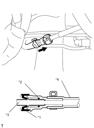
Text in Illustration *1 Retainer *2 O-ring *3 Fuel Pipe *4 Nylon Tube 
Pinch Connect the No. 2 fuel emission tube with the clamp.
Note
-
Check that there are no scratches or foreign objects on the connecting part.
-
Check that the No. 2 fuel emission tube is inserted securely.
-
-
-
CONNECT FUEL TANK MAIN TUBE SUB-ASSEMBLY
-
Line up the pipe and connector and push them together until a "click" sound is heard.
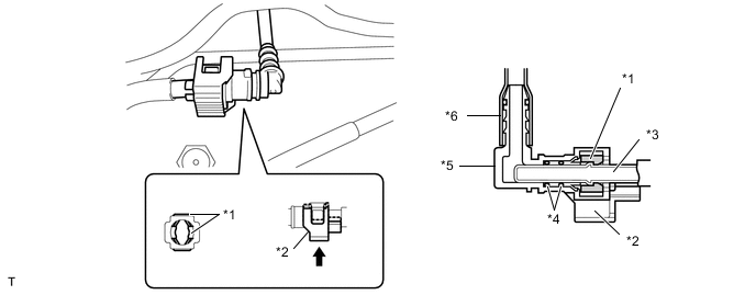
Text in Illustration *1 Retainer *2 Checker *3 Fuel Pipe *4 O-ring *5 Fuel Tube Connector *6 Nylon Tube Push -
Push the checker in to lock it.
Note
-
Check that there are no scratches or foreign objects on the connecting part.
-
Check that the fuel tank main tube is inserted securely.
-
After installing the checker, check that the fuel tank main tube is securely connected by pulling on it.
-
-
-
INSTALL FUEL TANK COVER VENT CASE SUB-ASSEMBLY
-
Install the fuel tank cover vent case sub-assembly with the bolt and clip.
- Torque:
- 5.4 N*m { 55 kgf*cm, 48 in.*lbf }
-
-
INSTALL FRONT NO. 4 FLOOR HEAT INSULATOR
-
Install the front No. 4 floor heat insulator with the 2 nuts.
- Torque:
- 5.4 N*m { 55 kgf*cm, 48 in.*lbf }
-
-
ADD FUEL
-
INSTALL FUEL SUCTION WITH PUMP AND GAUGE TUBE ASSEMBLY