FUEL INJECTOR INSTALLATION

PROCEDURE
-
INSTALL FUEL INJECTOR ASSEMBLY
-
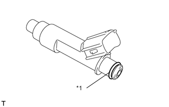
Text in Illustration *1 O-ring Apply a light coat of gasoline or spindle oil to new O-rings, and then install one onto each fuel injector assembly.
-
Apply a light coat of gasoline or spindle oil to the contact surfaces of the new O-ring on each fuel injector assembly.
-
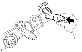
While turning the fuel injector assembly left and right, install it onto the fuel delivery pipe sub-assembly.
Text in Illustration 
Push 
Turn Note
-
Make sure that the O-ring is not cracked or pinched when installing the fuel injector assembly Click here.
-
If a part has been dropped or subjected to a strong impact, replace it.
-
-
Check that the fuel injector assembly rotates smoothly. If the fuel injector assembly does not rotate, replace the O-ring.
-
-
INSTALL INJECTOR VIBRATION INSULATOR
-
Install the 4 new injector vibration insulators onto the cylinder head.
-
-
INSTALL NO. 1 DELIVERY PIPE SPACER
-
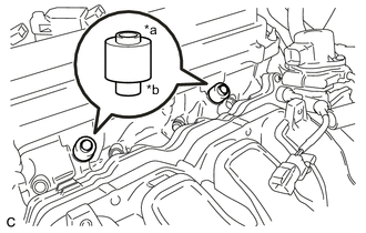
Text in Illustration *a Fuel Delivery Pipe Side *b Cylinder Head Side Install the 2 No. 1 delivery pipe spacers onto the cylinder head.
Note
Install the No. 1 delivery pipe spacer in the correct direction.
-
-
INSTALL FUEL DELIVERY PIPE SUB-ASSEMBLY
-
Install the fuel delivery pipe sub-assembly with the 4 fuel injector assemblies, and install the 2 bolts.
- Torque:
- 21 N*m { 214 kgf*cm, 15 ft.*lbf }
Note
-
Do not drop the fuel injector assemblies when installing the fuel delivery pipe sub-assembly.
-
Check that the fuel injector assemblies rotate smoothly after installing the fuel delivery pipe sub-assembly.
-
Install the fuel delivery pipe bracket with the bolt.
- Torque:
- 10 N*m { 102 kgf*cm, 7 ft.*lbf }
-
Install the wire harness bracket with the bolt.
- Torque:
- 8.4 N*m { 86 kgf*cm, 74 in.*lbf }
-
-
CONNECT FUEL TUBE SUB-ASSEMBLY
-
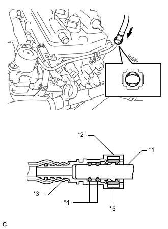
Text in Illustration *1 Fuel Pipe *2 Fuel Tube Connector *3 Nylon Tube *4 O-ring *5 Retainer Push the fuel tube connector into the fuel pipe until the fuel tube connector makes a "click" sound.
Note
-
Before connecting the fuel tube connector and fuel delivery pipe sub-assembly, check that there is no damage or foreign matter on the connecting part of the fuel delivery pipe sub-assembly.
-
After connecting the fuel tube connector and fuel delivery pipe sub-assembly, check that they are securely connected by trying to pull them apart.
-
-
Install the No. 1 EFI fuel pipe clamp.
-
-
CONNECT ENGINE WIRE
-
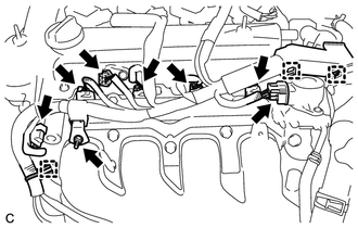
Connect the 3 wire harness clamps.
-
Install the wire harness bracket with the bolt.
- Torque:
- 11 N*m { 112 kgf*cm, 8 ft.*lbf }
-
Connect the camshaft oil control valve connector.
-
Connect the camshaft position sensor connector.
-
Connect the EGR valve connector.
-
Connect the 4 fuel injector assembly connectors.
-
-
CONNECT FUEL VAPOR FEED HOSE ASSEMBLY
-
Connect the fuel vapor feed hose assembly.
-
-
CONNECT VENTILATION HOSE
-
Connect the ventilation hose.
-
-
INSPECT FOR FUEL LEAK