FUEL PUMP INSTALLATION

CAUTION / NOTICE / HINT
Note
-
Be careful not to allow foreign matter to enter the fuel lines.
-
If the fuel filter is bent, the ability of the pump to produce suction will decrease and the pump may be damaged. Therefore, do not bend the fuel filter except when removing it from or installing it to the fuel tank.
PROCEDURE
-
INSTALL FUEL SUCTION TUBE SET GASKET
-
Install a new fuel suction tube gasket onto the fuel tank.
-
-
INSTALL FUEL SUCTION WITH PUMP AND GAUGE TUBE ASSEMBLY
-
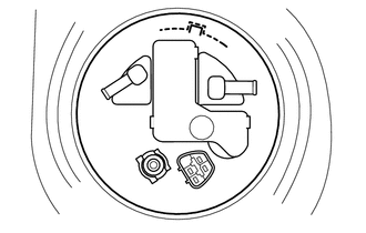
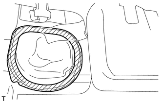
Text in Illustration *a Protrusion *b Groove Install the fuel suction with pump and gauge tube assembly to the fuel tank.
Tech Tips
When installing the fuel suction with pump and gauge tube assembly, bend the fuel filter as shown in the illustration and install it.
Note
-
Be careful not to bend the arm of the fuel sender gauge.
-
Do not bend the fuel filter more than necessary.
-
Do not bend the fuel filter in the opposite direction.
-
-
Align the protrusions of the fuel suction with pump and gauge tube assembly with the grooves of the fuel tank.
Note
Make sure that the fuel suction tube gasket is in the correct position.
-
-
INSTALL FUEL PUMP GAUGE RETAINER
-
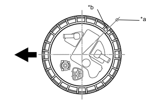
Text in Illustration *a Fuel Tank Mark *b Retainer Mark 
Front of Vehicle Put a retainer on the fuel tank. While holding the fuel suction with pump and gauge tube assembly, tighten the retainer one complete turn by hand.
-
Set SST on the fuel pump gauge retainer.
- SST
- 09808-14030
Note
-
Hold the fuel suction tube assembly upright by hand to ensure that the fuel suction tube gasket is not moved out of position.
-
Securely attach the claws of SST to the protrusions of the fuel pump gauge retainer and fix SST in place.
-
Install SST while pressing the claws of SST against the fuel pump gauge retainer (toward the center of SST).
-
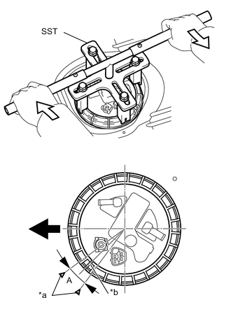
Text in Illustration *a Fuel Tank Mark *b Retainer Mark Front of Vehicle 
Turn Using SST, tighten the retainer until the mark on the retainer is within range A on the fuel tank as shown in the illustration.
- SST
- 09808-14030
-
-
CONNECT NO. 1 CANISTER OUTLET HOSE SUB-ASSEMBLY
-
Connect the No. 1 canister outlet hose.
-
-
CONNECT NO. 2 FUEL EMISSION TUBE
-
Connect the No. 2 fuel emission tube.
-
-
CONNECT FUEL TANK MAIN TUBE SUB-ASSEMBLY
-
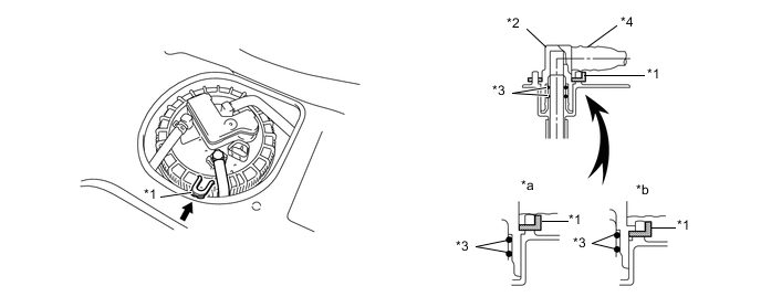
Insert the fuel tank main tube.
-
Install the tube joint clip.
Text in Illustration *1 Fuel Tube Joint Clip *2 Fuel Tube Joint *3 O-Ring *4 Fuel Tube *a CORRECT *b INCORRECT Note
-
Check that there are no scratches or foreign objects on the connecting part.
-
Check that the fuel tank main tube is inserted securely.
-
Check that the tube joint clip is on the collar of the main tube.
-
After installing the tube joint clip, check that the fuel tank main tube assembly is securely connected by pulling on it.
-
Do not damage any of the clips. If a clip is damaged, replace it.
-
-
-
INSTALL REAR FLOOR SERVICE HOLE COVER
-
Connect the fuel pump connector.
-
Install the rear floor service hole cover with new butyl tape.
-
-
INSTALL REAR SEAT ASSEMBLY LH
-
INSPECT FOR FUEL LEAK