FUEL SENDER GAUGE ASSEMBLY INSTALLATION

PROCEDURE
-
INSTALL FUEL SENDER GAUGE ASSEMBLY
-
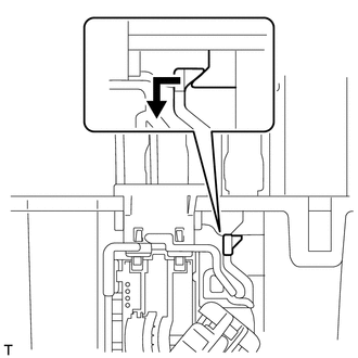
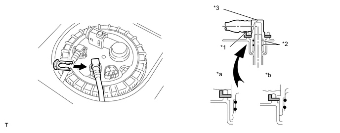
Install the fuel sender gauge by sliding it.
-
Connect the fuel sender gauge connector and engage the harness clamp.
-
-
INSTALL FUEL SUCTION TUBE SET GASKET
-
Install a new fuel tank suction tube gasket onto the fuel tank.
-
-
INSTALL FUEL TANK VENT TUBE WITH SENDER GAUGE ASSEMBLY
-
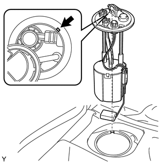
Align the protrusion of the fuel tank vent tube with sender gauge with the cutout of the fuel tank and install the fuel tank vent tube with sender gauge assembly.
Note
-
Do not bend the arm of the sender gauge.
-
Ensure that the fuel suction tube gasket is in the correct position.
-
-
-
INSTALL FUEL PUMP GAUGE RETAINER
-
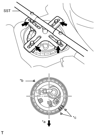
Text in Illustration *a Front Side *b Screw Starting Point *c Alignment Mark Align the end of the threads of a new fuel pump gauge retainer with that of the fuel tank.
- SST
- 09808-14030
-
While holding the fuel suction with pump and gauge tube assembly by hand, turn the retainer 180° clockwise by hand from the screw starting point and further turn it 360° clockwise using SST to align the claw of the retainer with the matchmark on the fuel tank.
Note
-
Replace the fuel pump gauge retainer with a new one if not turned 180° clockwise by hand. Part No. 77144-52030
-
Check that the contact surface of the fuel tank retainer is not scratched or damaged and prevent the entry of foreign objects.
Tech Tips
-
Align the ribs of the fuel pump gauge retainer with the tips of SST.
-
At the point where the retainer is turned 90° from the start of the thread, push the retainer in from the opposite side to the start of the thread. Check that the thread of the retainer is properly engaged with that on the tank.
-
-
-
CONNECT FUEL RETURN TUBE SUB-ASSEMBLY
-
Insert the fuel return tube.
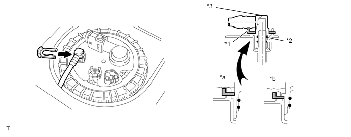
Text in Illustration *1 Tube Joint Clip *2 O-ring *3 Fuel Tube Connector *a OK *b NG -
Install the tube joint clip.
Note
-
Check that there are no scratches or foreign objects on the connecting part.
-
Check that the fuel return tube is inserted securely.
-
Check that the tube joint clip is on the collar of the fuel return tube.
-
After installing the tube joint clip, check that the fuel return tube assembly is securely connected by pulling on it.
-
Do not damage any of the clips. If a clip is damaged, replace it.
-
-
-
CONNECT FUEL TANK MAIN TUBE SUB-ASSEMBLY
-
Insert the fuel tank main tube.
Text in Illustration *1 Tube Joint Clip *2 O-ring *3 Fuel Tube Connector *a OK *b NG -
Install the tube joint clip.
Note
-
Check that there are no scratches or foreign objects on the connecting part.
-
Check that the fuel tank main tube is inserted securely.
-
Check that the tube joint clip is on the collar of the fuel tank main tube.
-
After installing the tube joint clip, check that the fuel tank main tube assembly is securely connected by pulling on it.
-
Do not damage any of the clips. If a clip is damaged, replace it.
-
-
-
INSTALL REAR FLOOR SERVICE HOLE COVER
-
Connect the fuel sender gauge connector.
-
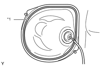
Text in Illustration *1 Butyl Tape Install the rear floor service hole cover with new butyl tape.
-
-
INSTALL REAR SEAT ASSEMBLY LH
-
BLEED AIR FROM FUEL SYSTEM
-
INSPECT FOR FUEL LEAK