CYLINDER BLOCK REASSEMBLY

PROCEDURE
-
INSTALL CYLINDER BLOCK WATER DRAIN COCK SUB-ASSEMBLY
-
Apply adhesive to the end 2 or 3 threads of the drain union and install the water drain cock within 3 minutes of applying the adhesive.
Adhesive Toyota Genuine Adhesive 1324, Three Bond 1324 or equivalent -
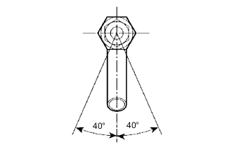
After applying the specified torque, rotate the drain union clockwise until the drain port faces downward.
- Torque:
- 35 N*m { 357 kgf*cm, 26 ft.*lbf }
Note
-
Do not put into coolant within 1 hour of installation.
-
Do not rotate the drain union more than 360° in step (b), and never loosen it after setting the union correctly.
-
-
INSTALL STRAIGHT PIN
-
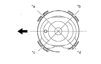
Using a plastic-faced hammer, tap in the straight pin.
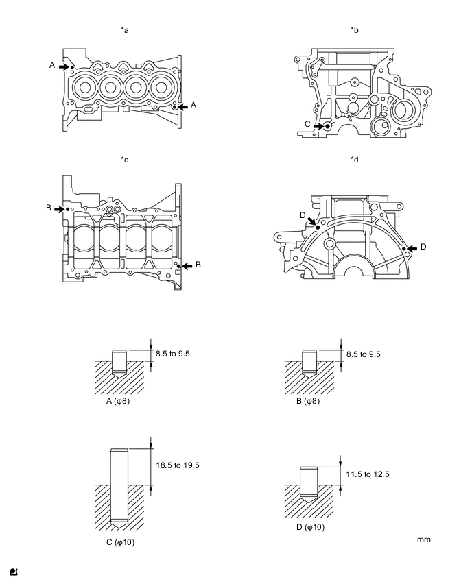
Text in Illustration *a Upper Side *b Front Side *c Lower Side *d Rear Side Standard protrusion Pin A 8.5 to 9.5 mm (0.335 to 0.374 in.) Pin B 8.5 to 9.5 mm (0.335 to 0.374 in.) Pin C 18.5 to 19.5 mm (0.728 to 0.768 in.) Pin D 11.5 to 12.5 mm (0.453 to 0.492 in.)
-
-
INSTALL OIL PUMP SET RING PIN
-
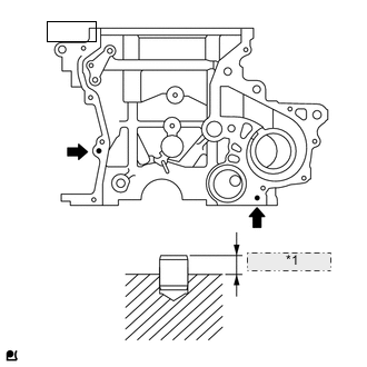
*1 3.5 to 4.5 mm Using a plastic-faced hammer, tap in a new ring pin.
Standard protrusion 3.5 to 4.5 mm (0.138 to 0.177 in.)
-
-
INSTALL STUD BOLT
-
Install the 7 stud bolts.
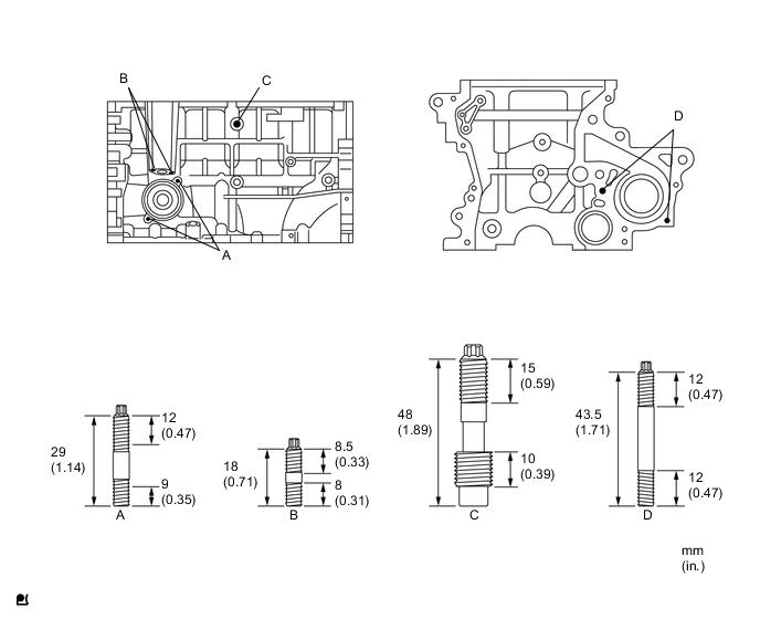
- Torque:
- Stud bolts A, B and D
- 5.0 N*m { 51 kgf*cm, 44 in.*lbf }
- Stud bolt C
- 11 N*m { 112 kgf*cm, 8 ft.*lbf }
Note
The lower threads of the bolt are installed into the cylinder block.
-
-
INSTALL CRANKSHAFT BEARING
-
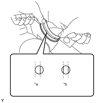
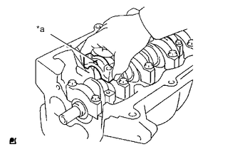
Align the crankshaft bearing (upper) with the oil hole of the cylinder block and install the bearing.
Text in Illustration *a Incorrect *b Correct Note
Do not apply engine oil to the bearing or its contact surface.
-
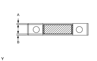
Align the crankshaft bearing (lower) with the bearing cap and install the crankshaft bearing cap.
Note
-
Install the bearing cap so that the gap between A and B is less than 0.4 mm (0.016 in.).
-
Do not apply engine oil to the bearing or its contact surface.
-
-
-
INSTALL CRANKSHAFT THRUST WASHER UPPER
-
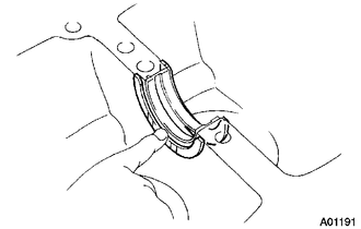
Install the 2 thrust washers onto the No. 3 journal position of the cylinder block with the oil grooves facing outward.
-
Apply engine oil to the upper bearing and install the crankshaft onto the cylinder block.
-
-
INSTALL CRANKSHAFT
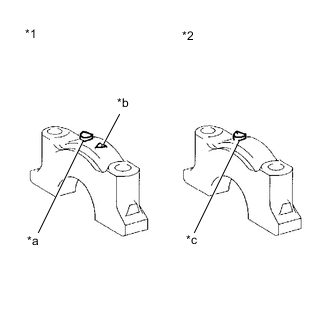
Text in Illustration *1 No. 3 Bearing Cap *2 No. 1,2,4,5 Bearing Cap *a Front Mark *b Number *c Front Mark and Number
-
Examine the front marks and numbers and install the bearing caps onto the cylinder block.
-
Apply a light coat of engine oil to the threads of the bearing cap bolts.
-
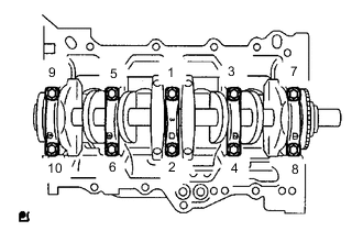
Tighten the bolts in several steps to the specified torque in the sequence shown in the illustration (*1).
- Torque:
- 22 N*m { 224 kgf*cm, 16 ft.*lbf }
Note
Check that the crankshaft turns smoothly.
-

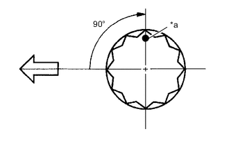
Text in Illustration *a Paint Mark 
Engine Front Mark the front of the bearing cap bolts with paint.
-
Further tighten the bearing cap bolts by 90° in the same sequence as step (*1).
-
Check that the painted mark is now at a 90° angle from the front.
-
-
INSPECT CRANKSHAFT THRUST CLEARANCE
-
INSPECT CRANKSHAFT OIL CLEARANCE
-
INSTALL WITH PIN PISTON SUB-ASSEMBLY
-
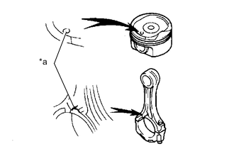
Text in Illustration *a Front Mark Coat the piston pin and pin holes in the piston with engine oil.
-
Align the cavity of the piston with the protruding portion on the connecting rod.
-
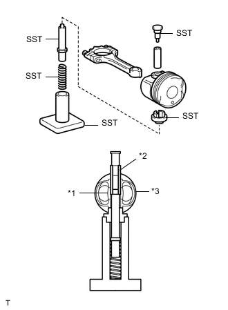
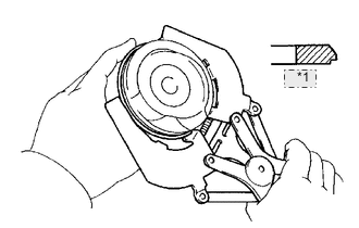
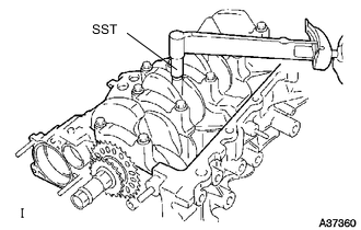
Text in Illustration *1 Connecting Rods *2 Piston Pin *3 Piston Using SST, press in the piston pin.
- SST
- 09221-25026 ( 09221-00021, 09221-00030, 09221-00150, 09221-00090, 09221-00100 )
-
-
INSTALL CONNECTING ROD BEARING
-
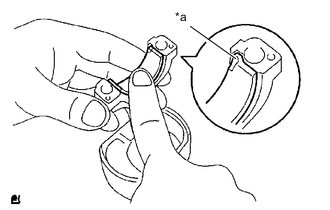
Text in Illustration *a Claw Align the bearing claw with the groove of the connecting rod or connecting cap.
Note
Clean the back side of the bearing and the bearing surface of the connecting rod and keep them free of oil.
-
-
INSTALL PISTON RING SET
*1 No. 2 Tech Tips
When reusing the piston rings, install them onto the matched pistons with the surfaces facing correctly.
-
Install the oil ring expander and 2 side rails by hand.
-
Using a piston ring expander, install the 2 compression rings.
-
Text in Illustration *a No. 1 Compression and Expander *b Lower Side Rail *c Upper Side Rail *d No. 2 Compression 
Engine Front Position the piston rings so that the ring ends are as shown.
-
-
INSTALL PISTON SUB-ASSEMBLY WITH CONNECTING ROD
-
Apply engine oil to the cylinder walls, the pistons, and the surfaces of connecting rod bearings.
-
Check the position of the piston ring ends.
-
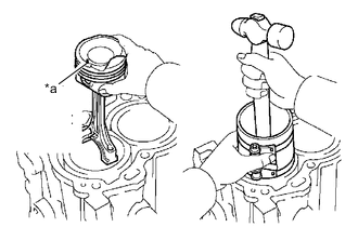
Text in Illustration *a Front Mark Using a piston ring compressor, push the correctly numbered piston and connecting rod assemblies into each cylinder with the front mark on the piston facing forward.
Note
-
Clean the back side of the bearing and the bearing surface of the connecting rod cap and keep them free of oil.
-
Match the numbered connecting rod cap with the connecting rod.
-
-
Text in Illustration *a Front Mark Make sure that the connecting rod and cap are in the correct combination and that the front mark of the cap is facing in the correct mounting orientation, then install the cap onto the connecting rod.
-
Apply a light coat of engine oil to the threads of the connecting rod cap bolts.
-
Using SST, tighten the bolts in several steps to the specified torque.
- SST
- 09205-16010
- Torque:
- 15 N*m { 153 kgf*cm, 11 ft.*lbf }
-
Text in Illustration *a Paint Mark Engine Front Mark the front of the connecting cap bolts with paint.
-
Further tighten the cap bolts by 90° as shown.
-
Check that the crankshaft turns smoothly.
-