CYLINDER BLOCK INSPECTION

PROCEDURE
-
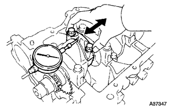
INSPECT CONNECTING ROD THRUST CLEARANCE
-
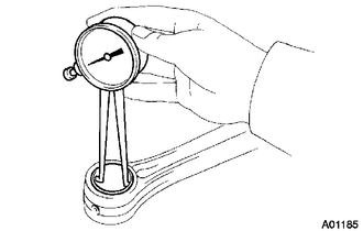
Using a dial indicator, measure the thrust clearance while moving the connecting rod back and forth.
Standard thrust clearance 0.16 to 0.36 mm (0.0063 to 0.0142 in.) Maximum thrust clearance 0.36 mm (0.0142 in.)
-
-
INSPECT CONNECTING ROD OIL CLEARANCE
-
Check that the matchmarks on the connecting rod and cap are aligned to ensure correct reassembly.
-
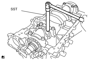
Using SST, remove the 2 connecting rod bolts.
- SST
- 09205-16011
-
Clean the crank pin and bearing.
-
Check the crank pin and bearing for pitting and scratches.
-
Text in Illustration *1 Plastigage Lay a strip of Plastigage across the crank pin.
-
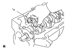
Text in Illustration *a Front Mark Make sure that the connecting rod and its cap are in the correct combination and that the front mark on the cap is facing in the correct mounting orientation, then install the cap onto the connecting rod.
-
Apply a light coat of engine oil to the threads of the connecting rod cap bolts.
-
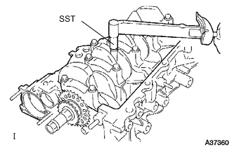
Using SST, tighten the connecting rod bolts in several steps to the specified torque.
- SST
- 09205-16011
- Torque:
- 15 N*m { 153 kgf*cm, 11 ft.*lbf }
-
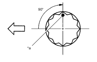
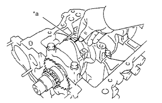
Text in Illustration *a Paint Mark 
Engine Front Mark the front of the connecting rod bolts with paint.
-
Further tighten the connecting rod bolts by 90° as shown in the illustration.
Note
Do not turn the crankshaft.
-
Remove the 2 bolts, connecting rod cap and lower bearing.
-
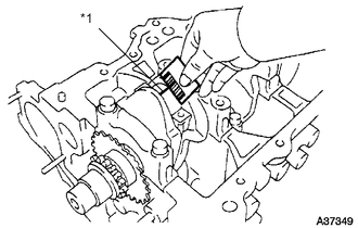
Text in Illustration *1 Plastigage Measure the plastigage at its widest point.
Standard oil clearance 0.012 to 0.034 mm (0.00047 to 0.0013 in.) Maximum oil clearance 0.054 mm (0.0022 in.) Note
Completely remove the plastigage after the measurement.
-
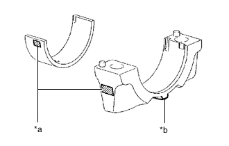
Text in Illustration *a Mark 1, 2 or 3 *b Front Mark When replacing a bearing, replace it with one with the same number as marked on the connecting rod. There are 3 sizes of standard bearings, marked 1, 2 and 3 accordingly.
Standard bearing center wall thickness Mark mm (in.) 1 1.491 to 1.494 (0.0587 to 0.0588) 2 1.494 to 1.497 (0.0588 to 0.0589) 3 1.497 to 1.500 (0.0589 to 0.0591) U/S 0.25 1.608 to 1.614 (0.0633 to 0.0635)
-
-
INSPECT CRANKSHAFT THRUST CLEARANCE
-
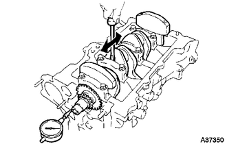
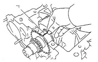
Using a dial indicator, measure the thrust clearance while moving the crankshaft back and forth with a screwdriver.
Standard thrust clearance 0.09 to 0.19 mm (0.0035 to 0.0075 in.) Maximum thrust clearance 0.30 mm (0.0118 in.) If the thrust clearance is greater than the maximum, replace the thrust washers as a set. Check the crankshaft and block for wear. Repair or replace the parts if necessary.
Tech Tips
Thrust washer thickness: 2.43 to 2.48 mm (0.0957 to 0.976 in.)
-
-
INSPECT CYLINDER BLOCK FOR WARPAGE
-
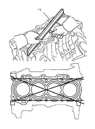
Text in Illustration *1 Straight Edge Using a precision straight edge and feeler gauge, measure the warpage of the surface which is in contact with the cylinder head gasket.
Maximum warpage 0.05 mm (0.0020 in.)
-
-
INSPECT CYLINDER BORE
-
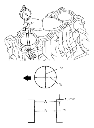
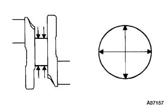
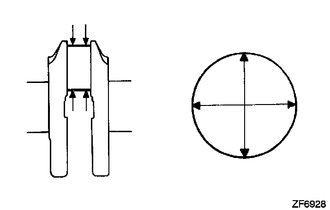
Text in Illustration *a Thrust Direction *b Axial Direction *c Center 
Engine Front Using a cylinder gauge, measure the cylinder bore diameter at positions A and B in the thrust and axial directions.
Standard inside diameter 75.000 to 75.013 mm (2.9528 to 2.9533 in.) Maximum inside diameter 75.133mm (2.9580in.)
-
-
INSPECT PISTON WITH PIN SUB-ASSEMBLY
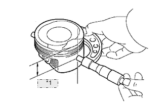
*1 36.7 mm
-
Using a micrometer, measure the piston diameter at a right angle to the piston pin center line, and at the position 36.7 mm (1.4449 in.) from top of the piston head.
Piston diameter 74.965 to 74.995 mm (2.9514 to 2.9526 in.) -
Using a caliper gauge, measure the piston pin hole diameter.
Piston pin hole diameter 18.013 to 18.016 mm (0.7092 to 0.7093 in.) at 20°C (68°F) -
Using a micrometer, measure the piston pin diameter.
Piston pin diameter 18.001 to 18.004 mm (0.7087 to 0.7088 in.) -
Subtract the piston pin diameter measurement from the piston pin hole diameter measurement to calculate the oil clearance.
Standard oil clearance 0.009 to 0.015 mm (0.0004 to 0.0006 in.) Maximum oil clearance 0.050 mm (0.0020 in.) If necessary, replace the piston and piston pin together.
-
-
INSPECT PISTON CLEARANCE
-
Subtract the piston diameter measurement from the cylinder bore diameter measurement to calculate the oil clearance.
Standard oil clearance 0.005 to 0.048 mm (0.00020 to 0.00189 in.) Maximum oil clearance 0.168 mm (0.0066 in.)
-
-
INSPECT CONNECTING ROD SUB-ASSEMBLY
-
Using a caliper gauge, measure the internal diameter of the connecting rod sub-assembly.
Standard connecting rod inside diameter 17.965 to 17.985 mm (0.707 to 0.708 in.) If the diameter is not within the range of the standard inside diameter, replace the connecting rod sub-assembly.
-
-
INSPECT RING GROOVE CLEARANCE
-
Using a feeler gauge, measure the clearance between a new piston ring and the wall of the ring groove.
Ring groove clearance No. 1 0.02 to 0.07 mm (0.0008 to 0.0028 in.) No. 2 0.02 to 0.06 mm (0.0008 to 0.0024 in.) Oil (Side Rail) 0.07 to 0.13 mm (0.0028 to 0.0052 in.)
-
-
INSPECT PISTON RING END GAP
-
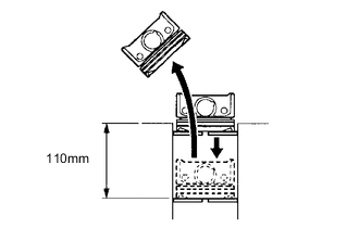
Using a piston, push the piston ring, a little beyond the bottom of the ring travel, 110 mm (4.33 in.) from the top of the cylinder block.
-
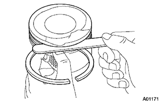
Using a feeler gauge, measure the end gap.
Standard end gap No. 1 0.20 to 0.30 mm (0.0078 to 0.0117 in.) No. 2 0.35 to 0.50 mm (0.0138 to 0.0197 in.) Oil (Side Rail) 0.10 to 0.35 mm (0.0039 to 0.0138 in.) Maximum end gap No. 1 0.49 mm (0.0191 in.) No. 2 1.06 mm (0.0417 in.) Oil (Side Rail) 0.71 mm (0.0277 in.)
-
-
INSPECT CONNECTING ROD BOLT
-
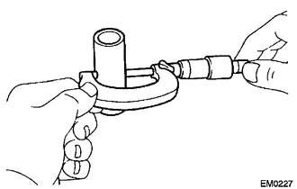
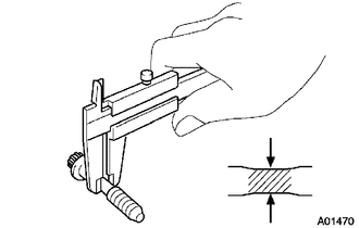
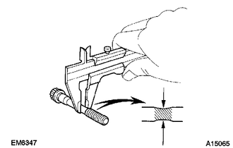
Using a vernier caliper, measure the diameter of the bolt at the elongated portion.
Standard diameter 6.6 to 6.7 mm (0.260 to 0.264 in.) Minimum diameter 6.4 mm (0.252 in.) If the diameter is less than the minimum, replace the connecting rod bolt.
-
-
INSPECT CRANKSHAFT
-
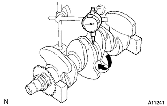
Using a dial indicator and V-blocks, measure the circle runout as shown in the illustration.
Maximum circle runout 0.03 mm (0.0012 in.) -
Using a micrometer, measure the diameter of each main journal.
Outside Diameter 45.988 to 46.000 mm (1.8106 to 1.8110 in.) -
Check each main journal for taper and out-of-roundness as shown.
Maximum taper and out-of-roundness 0.02 mm (0.0008 in.) -
Using a micrometer, measure the diameter of each crank pin.
Outside Diameter 39.992 to 40.000 mm (1.5745 to 1.5748 in.) -
Check each crank pin for taper and out-of-roundness as shown.
Maximum taper and out-of-roundness 0.02 mm (0.0008 in.) -
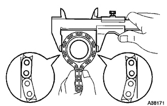
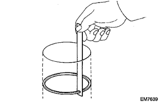
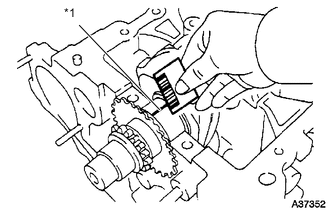
Wrap the chain around the timing sprocket.
-
Using a vernier caliper, measure the timing sprocket diameter with the chain sub-assembly.
Standard sprocket diameter (with chain sub-assembly) 51.72 mm (2.0362 in.) Minimum sprocket diameter (with chain sub-assembly) 50.5 mm (1.988 in.) Note
Make sure that the vernier calipers are in contact with the chain rollers when measuring.
-
-
INSPECT CRANKSHAFT BEARING CAP SET BOLT
-
Using a vernier caliper, measure the tension portion diameter at the elongated portion.
Standard diameter 7.3 to 7.5 mm (0.287 to 0.295 in.) Minimum diameter 7.2 mm (0.283 in.) If the diameter is less than minimum, replace the crankshaft bearing cap set bolt.
-
-
INSPECT CRANKSHAFT OIL CLEARANCE
-
Clean each main journal and bearing.
-
Install the bearing onto the cylinder block and bearing cap Click here.
-
Place the crankshaft onto the cylinder block.
-
Text in Illustration *1 Plastigage Lay a strip of plastigage across each journal.
-
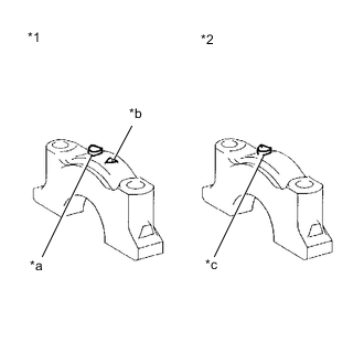
Text in Illustration *1 No. 3 Bearing Cap *2 No. 1, 2, 4, 5 Bearing Cap *a Front Mark *b Number *c Front Mark and Number Examine the front marks and numbers and install the bearing cap onto the cylinder block.
-
Apply a light coat of engine oil to the threads of the 10 crankshaft bearing cap set bolts.
-
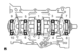
Using SST, tighten the bolts in several steps to the specified torque in the sequence shown in the illustration. (*1)
- Torque:
- 22 N*m { 224 kgf*cm, 16 ft.*lbf }
-

Text in Illustration *a Paint Mark Engine Front Mark the front of the crankshaft bearing cap set bolts with paint.
-
Further tighten the crankshaft bearing cap set bolts by 90° in the same sequence as step (*1).
-
Check that the painted mark is now at a 90° angle from the front.
Note
Do not turn the crankshaft.
-
Remove the crankshaft bearing cap sub-assembly.
-
Text in Illustration *1 Plastigage Measure the plastigage at its widest point.
Standard oil clearance 0.01 to 0.026mm (0.0004 to 0.00102 in.) Maximum oil clearance 0.07 mm (0.0028 in.) Note
Completely remove the plastigage after the measurement.
-
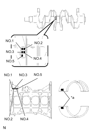
Text in Illustration *a Mark When replacing a standard bearing, replace it with one with the same number. If the number of the bearing cannot be found, select the correct bearing by adding together the numbers imprinted on the cylinder block and crankshaft, then select the bearing with the same number as the total. There are 4 sizes of standard bearings, marked 1, 2, 3 and 4 accordingly.
EXAMPLE: Cylinder Block 4 (A) + Crankshaft 3 (B) = Total 7 (Use Bearing 3) Cylinder Block (A)
+
Crankshaft (B)
0 to 2 3 to 5 6 to 8 9 to 11 Use Bearing 1 2 3 4 Item Mark mm (in.) Cylinder block main journal bore diameter (A) 0
1
2
3
4
5
6
50.000 to 50.003 (1.96850 to 1.96862)
50.003 to 50.005 (1.96862 to 1.96870)
50.005 to 50.007 (1.96870 to 1.96878)
50.007 to 50.010 (1.96878 to 1.96890)
50.010 to 50.012 (1.96890 to 1.96898)
50.012 to 50.014 (1.96898 to 1.96906)
50.014 to 50.016 (1.96906 to 1.96913)
Crankshaft main journal diameter (B) 0
1
2
3
4
5
45.998 to 46.000 (1.81094 to 1.81102)
45.996 to 45.998 (1.81087 to 1.81094)
45.994 to 45.996 (1.81079 to 1.81087)
45.992 to 45.994 (1.81071 to 1.81079)
45.990 to 45.992 (1.81063 to 1.81071)
45.988 to 45.990 (1.81055 to 1.81063)
Standard bearing center wall thickness 1
2
3
4
1.992 to 1.995 (0.07843 to 0.07854)
1.995 to 1.998 (0.07854 to 0.07866)
1.998 to 2.001 (0.07866 to 0.07878)
2.001 to 2.004 (0.07878 to 0.07890)
- U/S 0.25 2.111 to 2.117 (0.08311 to 0.08335)
-