CYLINDER BLOCK DISASSEMBLY

PROCEDURE
-
REMOVE PISTON SUB-ASSEMBLY WITH CONNECTING ROD
-
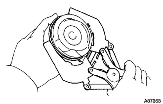
Using a ridge reamer, remove all the carbon from the top of the cylinder.
-
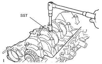
Using SST, remove the connecting rod cap bolt and cap.
- SST
- 09205-16010
-
Push the piston, connecting rod assembly and upper bearing through the top of the cylinder block to remove them.
Tech Tips
-
Keep the bearing, connecting rod and cap together.
-
Keep the piston and the connecting rod assemblies in the correct order so that they can be returned to their original locations when reassembled.
-
-
-
REMOVE CONNECTING ROD BEARING
-
REMOVE CRANKSHAFT
-
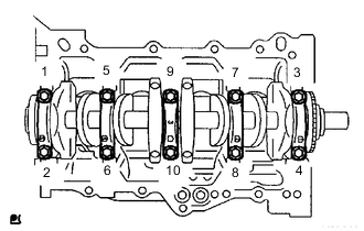
Using several steps, loosen and remove the 10 bearing cap sub-assembly bolts uniformly using SST in the sequence shown in the illustration.
- SST
- 09011-38121
-
Remove the bearing cap and the crankshaft.
-
-
REMOVE CRANKSHAFT BEARING
-
REMOVE CRANKSHAFT THRUST WASHER UPPER
-
REMOVE PISTON RING SET
Note
Keep the piston rings in the correct combination and correct order so that they can be returned to their original locations when re-assembling.
-
Using a piston ring expander, remove the 2 compression rings.
-
Remove the 2 side rails and the oil ring by hand.
-
-
REMOVE WITH PIN PISTON SUB-ASSEMBLY
-
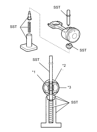
Text in Illustration *1 Connecting Rods *2 Piston Pin *3 Piston Using SST, press the piston pin out of the piston.
- SST
- 09221-25026 ( 09221-00021, 09221-00030, 09221-00150, 09221-00090, 09221-00100 )
Note
Keep the pistons, pins, rings, connecting rods and bearings in the correct order so that they can be returned to their original locations when reassembled.
-
-
REMOVE CYLINDER BLOCK WATER DRAIN COCK SUB-ASSEMBLY
-
REMOVE STUD BOLT
-
REMOVE OIL PUMP SET RING PIN
-
REMOVE STRAIGHT PIN