CYLINDER HEAD REASSEMBLY

PROCEDURE
-
INSTALL CAMSHAFT BEARING CAP SETTING RING PIN
-
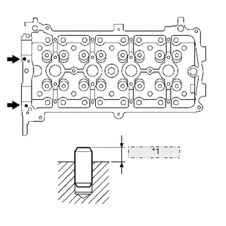
*1 4.5 to 5.5 mm Using a plastic-faced hammer, tap a 2 new camshaft bearing cap setting ring pins in to the specified protrusion height.
Protrusion height 4.5 to 5.5 mm (0.177 to 0.217 in.)
-
-
INSTALL STUD BOLT
-
Using "TORX" socket wrenches E5 and E7, install the 11 stud bolts.
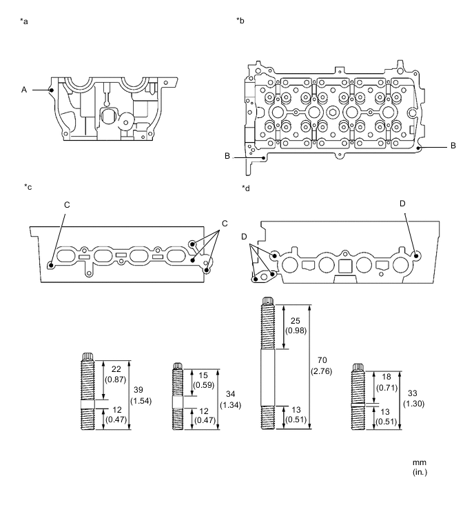
Text in Illustration *a Front Side *b Cylinder Head Upper Side *c Intake Manifold Side *d Exhaust Manifold Side - Torque:
- Bolt A and C
- 10 N*m { 102 kgf*cm, 7 ft.*lbf }
- Bolt B
- 4.0 N*m { 41 kgf*cm, 35 in.*lbf }
- Bolt D
- 9.0 N*m { 92 kgf*cm, 80 in.*lbf }
-
-
INSTALL VALVE STEM OIL SEAL
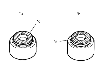
Text in Illustration *a Intake *b Exhaust *c Gray *d Black
-
Apply a light coat of engine oil to the valve stem oil seal.
Note
Installing the valve stem oil seal for intake and exhaust onto the opposite valve guide bush may cause failures.
Tech Tips
The intake valve stem oil seal is gray and the exhaust valve stem oil seal is black.
-
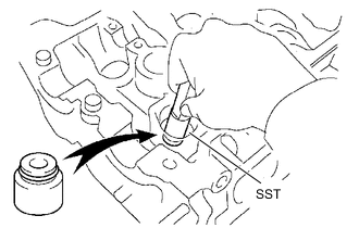
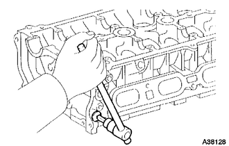
Using SST, push in a new valve stem oil seal.
- SST
- 09201-41020
-
-
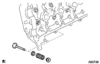
INSTALL INTAKE VALVE
-
Install the valve, valve spring seat, valve spring, and retainer.
Note
Install the parts into their original locations in the original order.
-
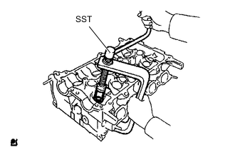
Using SST, compress the valve spring and place the 2 retainer locks around the valve stem.
- SST
- 09202-70020 ( 09202-00010 )
-
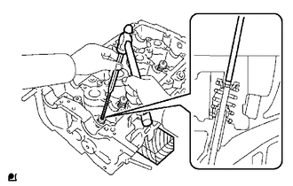
Using a plastic-faced hammer and the valve stem of another valve (not in use) with its tip wrapped in tape, gently tap the valve stem tip to ensure a proper fit.
Note
Do not damage the valve stem tip.
-
-
INSTALL EXHAUST VALVE
-
Install the valve, valve spring seat, valve spring, and retainer.
-
Using SST, compress the valve spring and place the 2 retainer locks around the valve stem.
- SST
- 09202-70020 ( 09202-00010 )
-
Using a pin-punch (5mm) and the valve stem (not in use) with the tip wrapped in tape, lightly tap the valve stem tip to ensure a proper fit.
Note
Do not damage the valve stem tip.
-
-
INSTALL VALVE STEM CAP
-
Apply a light coat of engine oil to the valve stem caps.
-
Install the 16 valve stem caps.
Note
Install the valve stem caps to their original locations in the original order.
-
-
INSTALL CYLINDER HEAD OIL NOZZLE
-
Install the cylinder head oil nozzle.
- Torque:
- 7.0 N*m { 71 kgf*cm, 62 in.*lbf }
-
-
INSTALL OIL CONTROL VALVE FILTER
-
Make sure that the mesh of the oil control valve filter is free of dirt or foreign matter.
-
Install the oil control valve filter.
-
-
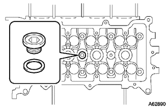
INSTALL NO. 2 WITH HEAD TAPER SCREW PLUG
-
Using an 8 mm hexagon wrench, install the No.2 head taper screw plug and a new gasket.
- Torque:
- 30 N*m { 306 kgf*cm, 22 ft.*lbf }
-
-
INSTALL NO. 1 WITH HEAD TAPER SCREW PLUG
-
Using a 10 mm socket hexagon wrench, install the No. 1 with head taper screw plug with a new gasket.
- Torque:
- 80 N*m { 816 kgf*cm, 59 ft.*lbf }
-
-
INSTALL VALVE LASH ADJUSTER ASSEMBLY
Note
-
Keep the valve lash adjuster free of dirt and foreign matter.
-
Only use clean engine oil.
-
Place the lash adjuster into a container filled with engine oil.
-
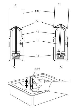
Text in Illustration *1 Plunger *2 Check Ball *3 Low Pressure Chamber *4 High Pressure Chamber *a Correct *b Incorrect *c Taper Part Insert the tip of SST into the lash adjuster plunger and use the tip to press down on the check ball inside the plunger.
- SST
- 09276-75010
-
Squeeze SST and the lash adjuster together to move the plunger up and down 5 to 6 times.
-
Check the movement of the plunger and bleed it.
OK Plunger moves up and down. Note
When bleeding air from the high-pressure chamber, make sure that the tip of SST is actually pressing the check ball as shown in the illustration. If the check ball is not pressed, the high-pressure chamber will not be bled.
-
After bleeding, remove SST. Then, try to press the plunger quickly and firmly with a finger.
OK Plunger is very difficult to move. If the result is not as specified, replace the valve lash adjuster assembly.
-
Install the valve lash adjuster assemblies.
Note
Install the lash adjusters to the their original locations.
-
-
INSTALL NO. 1 VALVE ROCKER ARM SUB-ASSEMBLY
-
Apply engine oil to the lash adjuster tips and valve stem cap ends.
-
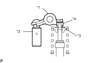
Text in Illustration *1 No. 1 Valve Rocker Arm Sub-assembly *2 Valve Lash Adjuster Assembly *3 Valve Stem *4 Valve Stem Cap Make sure that the No. 1 valve rocker arm subassemblies are installed as shown in the illustration.
-