CYLINDER HEAD INSPECTION

PROCEDURE
-
INSPECT CYLINDER HEAD FOR WARPAGE
-
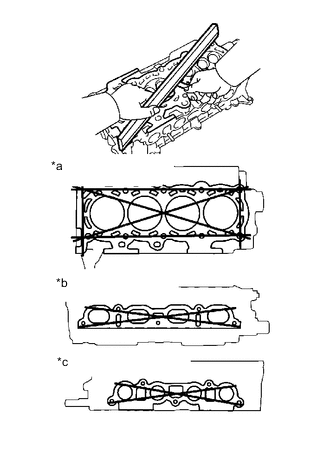
Text in Illustration *a Cylinder Block Side *b Intake Manifold Side *c Exhaust Manifold Side Using a precision straight edge and feeler gauge, measure the warpage of the surface that is in contact with the cylinder block and the manifolds.
Maximum warpage Surface Specified Condition Cylinder block side 0.05 mm (0.0020 in.) Intake manifold side 0.10 mm (0.0039 in.) Exhaust manifold side 0.10 mm (0.0039 in.) If the warpage is greater than the maximum, replace the cylinder head.
-
-
INSPECT CYLINDER HEAD FOR CRACKS
-
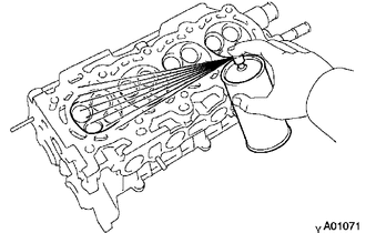
Using a dye penetrant, check the combustion chamber, intake ports, exhaust ports and cylinder block surface for cracks.
If cracked, replace the cylinder head.
-
-
INSPECT INTAKE VALVE
-
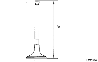
Text in Illustration *a Overall Length Check the overall valve length.
Standard overall length 102.15mm (4.0217 in.) Minimum overall length 101.85mm (4.0098 in.) If the overall length is less than the minimum, replace the intake valve.
-
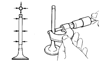
Using a micrometer, measure the diameter of the valve stem.
Standard valve stem diameter 5.470 to 5.485 mm (0.2154 to 0.2159 in.) -
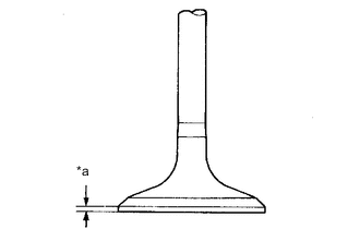
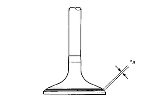
Text in Illustration *a Margin Thickness Check the valve head margin thickness.
Standard margin thickness 1.0 mm (0.039 in.) Minimum margin thickness 0.5 mm (0.020 in.) If the margin thickness is less than the minimum, replace the intake valve.
-
-
INSPECT EXHAUST VALVE
-
Check the overall valve length.
Standard overall length 103.3 mm (4.0669 in.) Minimum overall length 103.0 mm (4.0551 in.) If the overall length is less than the minimum, replace the exhaust valve.
-
Using a micrometer, measure the diameter of the valve stem.
Standard valve stem diameter 5.465 to 5.480 mm (0.2152 to 0.2157 in.) -
Check the valve head margin thickness.
Standard margin thickness 1.15 mm (0.045 in.) Minimum margin thickness 0.5 mm (0.020 in.) If the margin thickness is less than the minimum, replace the exhaust valve.
-
-
INSPECT VALVE SPRING
-
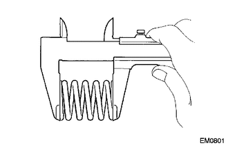
Using a vernier caliper, measure the free length of the valve spring.
Standard free length 49.22 to 51.22 mm (1.9378 to 2.0165 in.) If the free length is not as specified, replace the valve spring.
-
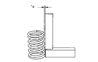
Text in Illustration *a Deviation Using a steel square, measure the deviation of the valve spring.
Maximum deviation 1.6 mm (0.063 in.) Maximum angle (reference) 2° If the deviation is greater than the maximum, replace the valve spring.
-
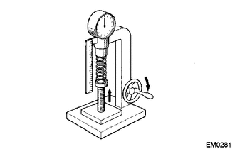
Using a spring tester, measure the tension of the valve spring at the specified installed length.
Standard installed tension 168 to 185 N (17.1 to 18.9 kgf, 37.7 to 41.7 lbf) at 36.5 mm (1.437 in.) Maximum working tension 313 to 347 N (31.9 to 35.4 kgf, 70.4 to 78 lbf) at 27 mm (1.063 in.) If the installed tension is not as specified, replace the valve spring.
-
-
INSPECT VALVE GUIDE BUSH OIL CLEARANCE
-
Using a caliper gauge, measure the inside diameter of the valve guide bush.
Bush inside diameter 5.510 to 5.530 mm (0.2169 to 0.2177 in.) -
Subtract the valve stem diameter measurement from the valve guide bush inside diameter measurement.
Standard oil clearance Guide Bush Specified Condition Intake 0.025 to 0.060 mm
(0.0010 to 0.0024 in.)
Exhaust 0.030 to 0.065 mm
(0.0012 to 0.0026 in.)
Maximum oil clearance Guide Bush Specified Condition Intake 0.08 mm (0.0032 in.) Exhaust 0.10 mm (0.0039 in.) If the clearance is greater than the maximum, replace the valve and valve guide bush Click here.
-
-
INSPECT INTAKE VALVE SEAT AND EXHAUST VALVE SEAT
-
Apply a light coat of prussian blue to the valve face.
-
Lightly press the valve against the seat.
-
Text in Illustration *a Width Check the valve face and seat according to the following procedure.
-
If blue appears 360° around the face, the valve is concentric. If not, replace the valve.
-
If blue appears 360° around the valve seat, the guide and face are concentric. If not, resurface the seat.
-
Check that the seat contact is in the middle of the valve face with the width between 1.0 to 1.4 mm (0.039 to 0.055 in.).
-
-
-
INSTALL NO. 1 VALVE ROCKER ARM SUBASSEMBLY
-
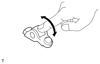
Turn the roller by hand to check that it turns smoothly.
Tech Tips
If the roller does not turn smoothly, replace the No. 1 valve rocker arm sub-assembly.
-
-
INSPECT VALVE LASH ADJUSTER ASSEMBLY
Note
-
Keep the valve lash adjuster assembly free of dirt and foreign matter.
-
Only use clean engine oil.
-
Place the lash adjuster into a container filled with engine oil.
-
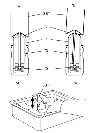
Text in Illustration *1 Plunger *2 Check Ball *3 Low Pressure Chamber *4 High Pressure Chamber *a Correct *b Incorrect *c Taper Part Insert the tip of SST into the lash adjuster plunger and use the tip to press down on the check ball inside the plunger.
- SST
- 09276-75010
-
Squeeze SST and the lash adjuster together to move the plunger up and down 5 to 6 times.
-
Check the movement of the plunger and bleed it.
OK Plunger moves up and down. Note
When bleeding air from the high-pressure chamber, make sure that the tip of SST is actually pressing the check ball as shown in the illustration. If the check ball is not pressed, the high-pressure chamber will not be bled.
-
After bleeding, remove SST. Then try to quickly and firmly press the plunger with a finger.
OK Plunger is very difficult to move. If the result is not as specified, replace the valve lash adjuster assembly.
-
-
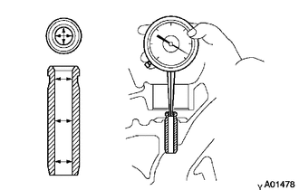
INSPECT CAMSHAFT THRUST CLEARANCE
-
Install the camshafts Click here.
-
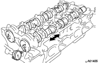
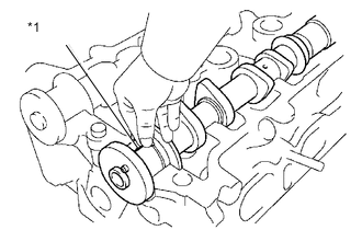
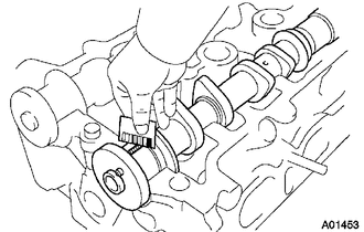
Using a dial indicator, measure the thrust clearance while moving the camshaft back and forth.
Standard thrust clearance 0.040 to 0.095 mm (0.0016 to 0.0037 in.) Maximum thrust clearance 0.11 mm (0.0043 in.) If the thrust clearance is greater than the maximum, replace the camshaft. If necessary, replace the bearing caps and the cylinder head together.
-
-
INSPECT CAMSHAFT OIL CLEARANCE
-
Clean the bearing caps and the camshaft journals.
-
Place the camshafts on the cylinder head sub-assembly.
-
Text in Illustration *1 Plastigage Lay a strip of Plastigage across each of the camshaft journals.
-
Install the bearing caps Click here.
Note
Do not turn the camshaft.
-
Remove the bearing caps.
-
Measure the Plastigage at its widest point.
Standard oil clearance 0.035 to 0.072 mm (0.0014 to 0.0028 in.) Maximum oil clearance 0.08 mm (0.0031 in.) If the oil clearance is greater than the maximum, replace the camshaft. If necessary, replace the bearing caps and the cylinder head together.
Note
Completely remove the Plastigage.
-