ENGINE UNIT INSTALLATION

PROCEDURE
-
INSTALL V-RIBBED BELT TENSIONER ASSEMBLY
-
Install the V-ribbed belt tensioner assembly with the 2 bolts.
- Torque:
- 21 N*m { 214 kgf*cm, 15 ft.*lbf }
-
-
INSTALL DRIVE SHAFT HEAT INSULATOR BRACKET
-
Install the drive shaft heat insulator bracket with the bolt and nut.
- Torque:
- 18 N*m { 179 kgf*cm, 13 ft.*lbf }
-
-
INSTALL NO. 1 WATER HOSE CLAMP BRACKET
-
Install the No. 1 water hose clamp bracket with the bolt.
- Torque:
- 18 N*m { 179 kgf*cm, 13 ft.*lbf }
-
-
CONNECT NO. 3 WATER BY-PASS HOSE
-
Connect the No. 3 water by-pass hose to the connector tube with the hose clamp.
-
-
INSTALL EXHAUST MANIFOLD
-
INSTALL MANIFOLD SUPPORT BRACKET
-
INSTALL DRIVE SHAFT HEAT INSULATOR SUB-ASSEMBLY
-
INSTALL NO. 1 EXHAUST MANIFOLD HEAT INSULATOR
-
INSTALL NO. 1 OUTLET WATER STAY
-
Install No. 1 outlet water stay with the bolt.
- Torque:
- 9.0 N*m { 92 kgf*cm, 80 in.*lbf }
-
-
INSTALL WIRE HARNESS CLAMP BRACKET
-
Install the wire harness clamp bracket with the bolt.
- Torque:
- 8.4 N*m { 86 kgf*cm, 74 in.*lbf }
-
-
INSTALL BOOSTER VACUUM TUBE
-
Install the booster vacuum tube with the 2 bolts.
- Torque:
- 9.0 N*m { 92 kgf*cm, 80 in.*lbf }
-
-
INSTALL MANIFOLD ABSOLUTE PRESSURE SENSOR
-
Install the manifold absolute pressure sensor with the nut.
- Torque:
- 7.5 N*m { 76 kgf*cm, 66 in.*lbf }
-
-
INSTALL NO. 1 OIL PIPE
-
INSTALL NO. 1 WATER BY-PASS PIPE
-
INSTALL EGR DELIVERY CHAMBER
-
Install the EGR delivery chamber and new No. 1 intake manifold gasket.
-
-
INSTALL ENGINE OIL LEVEL DIPSTICK GUIDE
-
Install the engine oil level dipstick guide with the bolt.
-
-
INSTALL NO. 2 INTAKE MANIFOLD INSULATOR
-
INSTALL INTAKE MANIFOLD
-
CONNECT UNION TO CONNECTOR TUBE HOSE
-
INSTALL ENGINE OIL LEVEL DIPSTICK SUB-ASSEMBLY
-
Install the engine oil level dipstick sub-assembly.
-
-
INSTALL NO. 1 IGNITION COIL
-
INSTALL EGR VALVE ASSEMBLY
-
INSTALL GENERATOR BRACKET
-
Install the generator bracket with the bolt.
- Torque:
- 11 N*m { 112 kgf*cm, 8 ft.*lbf }
-
-
INSTALL GENERATOR ASSEMBLY
-
INSTALL ENGINE WIRE
-
Connect all sensor connectors and wire harness clamps to the engine assembly and install the engine wire harness.
-
-
CONNECT OUTLET WATER BY-PASS
-
CONNECT INLET HEATER WATER HOSE A
-
Connect the inlet heater water hose A to the cylinder head with the hose clamp.
-
-
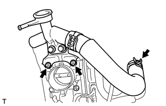
INSTALL WATER FILLER SUB-ASSEMBLY
-
Connect the No. 1 radiator hose to the cylinder head sub-assembly.
-
Install the water filler sub-assembly with 2 nuts.
- Torque:
- 7.5 N*m { 76 kgf*cm, 66 in.*lbf }
-