ENGINE UNIT REASSEMBLY

PROCEDURE
-
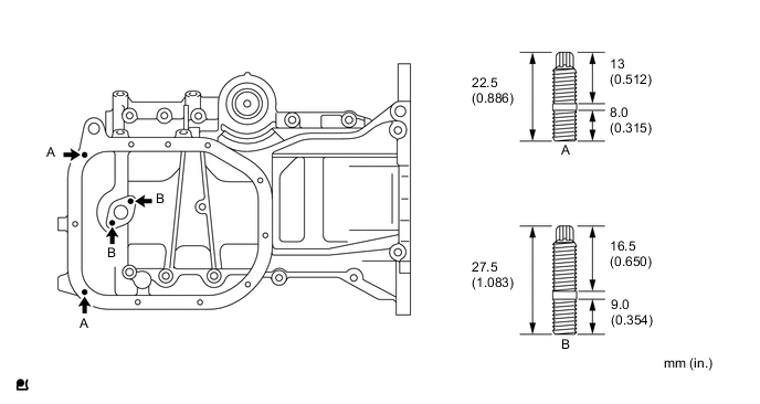
INSTALL STUD BOLT
-
Using "TORX" socket wrench E5, install the 4 stud bolts.
- Torque:
- 5.0 N*m { 51 kgf*cm, 44 in.*lbf }
-
-
INSTALL OIL PAN SUB-ASSEMBLY
-
Remove any old packing material from the contact surface.
-
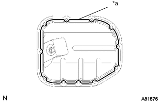
Text in Illustration *a Seal Packing Apply a continuous bead of seal packing to the oil pan mating surface as shown in the illustration.
Seal packing Toyota Genuine Seal Packing Black, Three Bond 1207B or equivalent Note
-
Remove any oil from the contact surface.
-
Install the oil pan within 3 minutes of applying seal packing.
-
Do not expose the seal to engine oil for at least 2 hours after the installation.
-
-
Install 2 new O-rings onto the cylinder block.
-
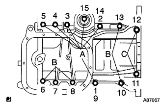
Using several steps, install and tighten the 13 bolts uniformly in the sequence shown in the illustration.
- Torque:
- 24 N*m { 245 kgf*cm, 18 ft.*lbf }
Tech Tips
Each bolt length is as follows:
Bolt A 49 mm (1.93 in.)
Bolt B 88 mm (3.47 in.)
Bolt C 144 mm (5.67 in.)
-
-
INSTALL OIL STRAINER SUB-ASSEMBLY
-
Install a new gasket and the oil strainer with the 2 nuts and the bolt.
- Torque:
- 11 N*m { 112 kgf*cm, 8 ft.*lbf }
-
-
INSTALL NO. 2 OIL PAN SUB-ASSEMBLY
-
Remove any old packing material from the contact surface.
-
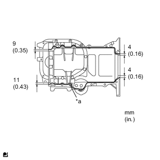
Text in Illustration *a Seal Packing Apply a continuous bead of seal packing (Diameter 2.5 to 3.5 mm (0.0984 to 0.1378 in.)) to the oil pan mating surface as shown in the illustration.
Seal packing Toyota Genuine Seal Packing Black, Three Bond 1207B or equivalent Note
-
Remove any oil from the contact surface.
-
Install the oil pan within 3 minutes of applying seal packing.
-
Do not expose the seal to engine oil within 2 hours of installation.
-
Do not start the engine for at least 2 hours after the installation.
-
-
Install the No. 2 oil pan with the 9 bolts and the 2 nuts.
- Torque:
- 9.0 N*m { 92 kgf*cm, 80 in.*lbf }
-
Install the drain plug with a new gasket.
- Torque:
- 38 N*m { 382 kgf*cm, 28 ft.*lbf }
-
-
INSTALL OIL FILTER UNION
-
Using a 12 mm (0.47 in.) hexagon wrench, install the oil filter union.
- Torque:
- 30 N*m { 306 kgf*cm, 22 ft.*lbf }
-
-
INSTALL OIL FILTER SUB-ASSEMBLY
-
Check and clean the oil filter installation surface.
-
Apply clean engine oil to the gasket of a new oil filter.
-
Gently screw the oil filter into place, and tighten it until the gasket comes into contact with the seat.
-
Using SST, tighten it an additional 3/4 turn.
- SST
- 09228-06501
Tech Tips
When using a torque wrench, tighten it to the specified torque.
- Torque:
- 13 N*m { 133 kgf*cm, 10 ft.*lbf }
-
-
INSTALL CYLINDER HEAD GASKET
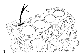
Text in Illustration *a Lot. No.
-
Place a new cylinder head gasket on the cylinder block with the Lot No. stamp facing upward.
Note
-
Remove any oil from the contact surface.
-
Pay attention to the mounting orientation of the cylinder head gasket.
-
Do not damage the cylinder gasket when installing the cylinder head onto the cylinder block.
-
-
-
INSTALL CYLINDER HEAD SUB-ASSEMBLY
Tech Tips
The cylinder head bolts are tightened in 2 successive steps.
-
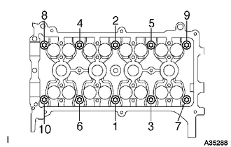
Apply a light coat of engine oil to the threads of the cylinder head bolts.
-
Using several steps, install and tighten the 10 cylinder head bolts and plate washers uniformly with an 8 mm bi-hexagon wrench in the sequence shown in the illustration.
- Torque:
- 29 N*m { 300 kgf*cm, 22 ft.*lbf }
-
Mark the front of the cylinder head bolt with paint.
-
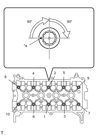
Text in Illustration *a Paint Mark Further tighten the cylinder head bolts by an additional 90° and one more additional 90° as shown in the illustration.
-
Check that the paint mark is now at a 180° angle from the front.
-

Text in Illustration *1 Cylinder Head *2 Cylinder Head Gasket *3 Cylinder Block *a Diameter 
Seal Packing Apply a continuous bead of seal packing (Diameter 4.5 to 5.5 mm (0.177 to 0.217 in.)) as shown in the illustration.
Seal Packing Toyota Genuine Seal Packing Black, Three Bond 1207B or equivalent Note
-
Remove any oil from the contact surface.
-
Install the oil pump assembly within 3 minutes and tighten the bolts within 15 minutes of applying seal packing.
-
-
-
INSTALL ENGINE REAR OIL SEAL
-
Apply MP grease to a new oil seal lip.
Note
Keep the lip free of foreign matter.
-
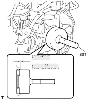
*1 0 to -1 mm *2 (0 to -0.04 in.) Using SST and a hammer, tap in the oil seal until its surface is flush with the cylinder block and oil pan.
- SST
- 09223-56010
Note
-
Do not tap the oil seal at an angle.
-
Wipe any extra grease off the crankshaft.
-
-
INSTALL VALVE STEM CAP
-
INSTALL VALVE LASH ADJUSTER ASSEMBLY
-
INSTALL NO. 1 VALVE ROCKER ARM SUB-ASSEMBLY
-
INSTALL CAMSHAFT TIMING GEAR ASSEMBLY
Note
Install the camshaft timing gear assembly onto the camshaft with the lock pin of the camshaft timing gear assembly released.
-
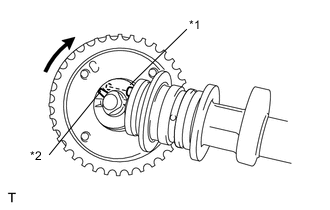
Text in Illustration *1 Straight Pin *2 Groove Put the camshaft timing gear assembly and camshaft together with the straight pin of the groove.
-
Turn the camshaft timing gear assembly clockwise while pushing it gently toward the camshaft. When the pin fits into the groove, push to ensure a good fit.
Note
Do not turn the camshaft timing gear in the retard direction (to the right).
-
Check that there is no clearance between the gear fringe and the camshaft.
-
Tighten the fringe bolt with the camshaft timing gear fixed.
- Torque:
- 64 N*m { 653 kgf*cm, 47 ft.*lbf }
Note
-
Do not lock the camshaft timing gear assembly when tightening the bolt.
-
Release the lock pin of the camshaft timing gear assembly first, and tighten the bolt when the lock pin is locked in the most retarded position.
-
Tightening the bolts with the lock pin locked could cause breakage of the lock pin.
-
Check that the camshaft timing gear assembly can move in the retard direction (to the right) and is locked in the most retarded position.
-
-
INSTALL CAMSHAFT
-
Apply a light coat of engine oil to the camshaft journals.
-
Place the camshaft on the cylinder head with the timing mark on the camshaft timing gear facing upward.
-
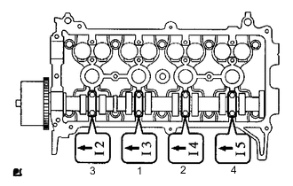
Examine the front marks and numbers and tighten the bolts in the sequence shown in the illustration.
- Torque:
- 13 N*m { 129 kgf*cm, 9 ft.*lbf }
Note
Tighten each bolt uniformly while keeping the camshaft level.
-
-
INSTALL CAMSHAFT TIMING SPROCKET
-
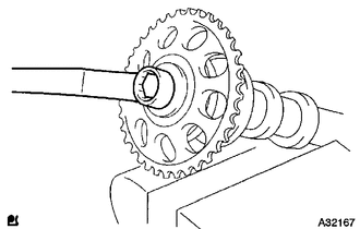
Clamp the camshaft in a vise.
-
Align the knock pin hole the camshaft timing sprocket with the knock pin of the camshaft, and install the camshaft timing sprocket with the fringe bolt.
- Torque:
- 64 N*m { 653 kgf*cm, 47 ft.*lbf }
Note
Do not damage the camshaft.
-
-
INSTALL NO. 2 CAMSHAFT
-
Apply a light coat of engine oil to the camshaft journals.
-
Place the camshaft on the cylinder head with the timing mark on the camshaft timing gear facing upward.
-
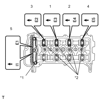
Text in Illustration *1 No. 1 Bearing Cap *2 No. 2 Bearing Cap Examine the front marks and numbers on the No. 1 and No. 2 camshaft bearing caps and check that the order is as shown in the illustration. Then uniformly tighten the bolts, in several steps, in the sequence shown in the illustration.
- Torque:
- 13 N*m { 129 kgf*cm, 9 ft.*lbf }
- for No. 2 bearing cap
- 23 N*m { 235 kgf*cm, 17 ft.*lbf }
- for No. 1 bearing cap
Note
Tighten each bolt uniformly while keeping the camshaft level.
-
-
INSTALL CAMSHAFT POSITION SENSOR
-
Apply engine oil to the O-ring.
Note
If the O-ring is damaged, replace the camshaft position sensor.
-
Install the camshaft position sensor with the bolt.
- Torque:
- 8.0 N*m { 82 kgf*cm, 71 in.*lbf }
-
-
INSTALL CHAIN SUB-ASSEMBLY

-
Make sure that all the timing marks are in the positions (TDC) shown in the illustration.
Text in Illustration *a TDC *b Timing Mark Tech Tips
The positions of the timing marks may differ the predetermined positions due to the force of the valve spring.
-
Text in Illustration *a Timing Mark *b 40° to140° ATDC Set the timing mark of the crankshaft in a position between 40 and 140° ATDC, as illustrated.
-
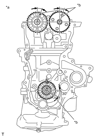
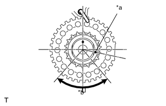
Text in Illustration *a 20° ATDC *b Timing Mark Set the camshaft timing gear and the camshaft timing sprocket in the positions (20° ATDC) shown in the illustration.
-
Set the crankshaft in the position (20° ATDC) shown in the illustration.
-
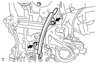
Install the No. 1 chain vibration damper with the 2 bolts.
- Torque:
- 9.0 N*m { 92 kgf*cm, 80 in.*lbf }
-
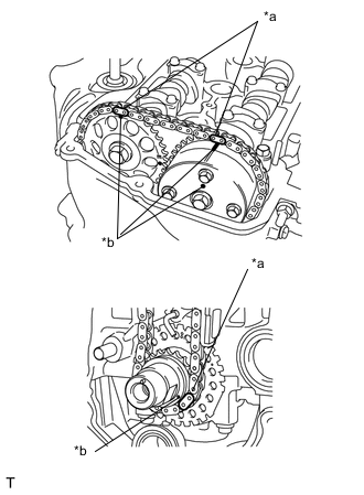
Text in Illustration *a Mark Plates *b Timing Mark Align the timing marks of the camshaft with the mark plates of the timing chain and install the timing chain.
Tech Tips
Align the timing marks with the mark plates while turning the hexagonal service portion of the camshaft using a wrench.
-
-
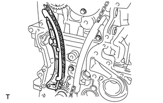
INSTALL CHAIN TENSIONER SLIPPER
-
Install the chain tensioner slipper.
-
-
INSTALL NO. 1 CHAIN TENSIONER ASSEMBLY
-
Install the No. 1 chain tensioner assembly with the 2 bolts.
- Torque:
- 9.0 N*m { 92 kgf*cm, 80 in.*lbf }
-
Remove the bar from the No. 1 chain tensioner assembly.
-
-
INSTALL OIL PUMP SEAL
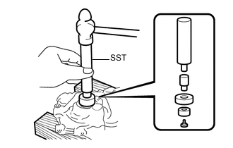
-
Using SST and a hammer, tap in a new oil seal until its surface is flush with the timing chain cover.
- SST
- 09950-60010 ( 09951-00250, 09951-00380, 09952-06010 )
- 09950-70010 ( 09951-07100 )
Note
-
Do not tap the oil seal at an angle.
-
Keep the lip free of foreign matter.
-
Apply MP grease to the oil seal lip.
-
-
INSTALL OIL PUMP ASSEMBLY
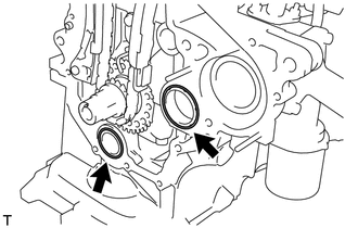
-
Install 2 new O-rings onto the 2 locations shown in the illustration.
-
Apply seal packing to the oil pump assembly, cylinder head and cylinder block as shown in the illustration.
Seal packing Water pump part Toyota Genuine Seal Packing 1282B, Three Bond 1282B or equivalent Other part Toyota Genuine Seal Packing Black, Three Bond 1207B or equivalent Note
-
Remove any oil from the contact surface.
-
Install the oil pump assembly within 3 minutes and tighten the bolts and nut within 15 minutes of applying the seal packing.
-
Do not expose the seal to engine oil for at least 2 hours after the installation.
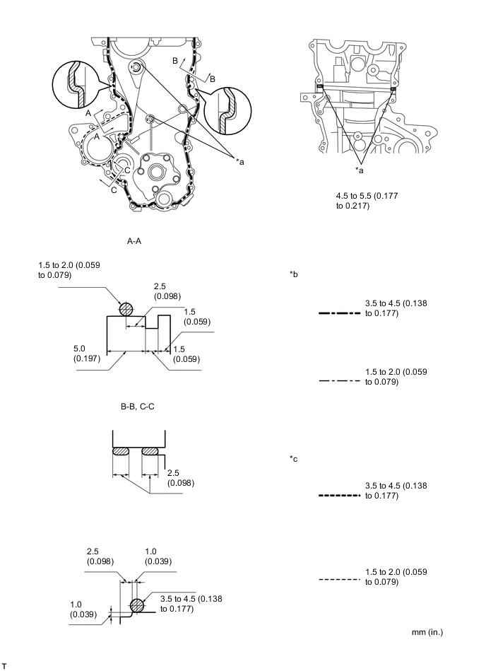
Text in Illustration *a Seal Packing *b Seal Width (Other Part) *c Seal Width (Water Pump Part) - - -
-
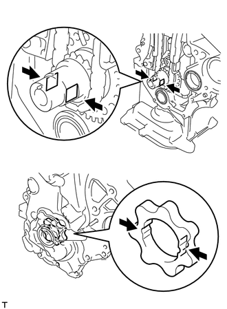
Align the keyway of the oil pump rotor with the rectangular portion of the crankshaft, and slide the oil pump into place.
-
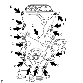
Install the oil pump assembly with the 15 bolts and nut. Tighten the bolts and nut uniformly in several steps.
- Torque:
- 32 N*m { 326 kgf*cm, 24 ft.*lbf }
- for bolt A
- 11 N*m { 112 kgf*cm, 8 ft.*lbf }
- for bolt B
- 11 N*m { 112 kgf*cm, 8 ft.*lbf }
- for bolt C
- 24 N*m { 245 kgf*cm, 18 ft.*lbf }
- for nut D
- 24 N*m { 245 kgf*cm, 18 ft.*lbf }
- for bolt E
Note
Install the mounting bracket and water pump within 15 minutes of installing the oil pump assembly.
Tech Tips
Each bolt length is as follows.
A: 30 mm (1.181 in.)
B: 35 mm (1.378 in.)
C: 20 mm (0.787 in.)
E: 20 to 14 mm (0.787 to 0.551 in.) Double ended bolt
-
-
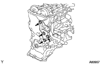
INSTALL WATER PUMP ASSEMBLY
-
Install the water pump and a new gasket with the 3 bolts and 2 nuts.
- Torque:
- 11 N*m { 112 kgf*cm, 8 ft.*lbf }
-
-
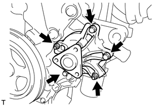
INSTALL TRANSVERSE ENGINE ENGINE MOUNTING BRACKET
-
Install the transverse engine engine mounting bracket with the 4 bolts.
- Torque:
- 55 N*m { 561 kgf*cm, 41 ft.*lbf }
-
-
INSTALL CRANKSHAFT DAMPER SUB-ASSEMBLY
-
Align the pin hole in the crankshaft damper with the pin position and install the crankshaft damper sub-assembly.
-
Provisionally install the bolt.
-
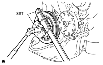
Using 2 SSTs, tighten the bolt while holding the crankshaft damper sub-assembly.
- SST
- 09213-14010 ( 91651-60865 )
- 09330-00021
- Torque:
- 128 N*m { 1310 kgf*cm, 95 ft.*lbf }
Note
Check the SST installation positions when installing them, to avoid the SST fixing bolts from coming into contact with the oil pump assembly.
-
-
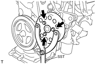
INSTALL WATER PUMP PULLEY
-
Using SST, install the water pump pulley with the 3 bolts.
- Torque:
- 15 N*m { 153 kgf*cm, 11 ft.*lbf }
- SST
- 09960-10010 ( 09962-01000, 09963-00700 )
-
-
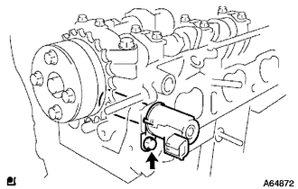
INSTALL CAMSHAFT TIMING OIL CONTROL VALVE ASSEMBLY
-
Apply a light coat of engine oil to a new O-ring, and install it onto the camshaft timing oil control valve.
-
Install the camshaft timing oil control valve with the bolt.
- Torque:
- 7.5 N*m { 76 kgf*cm, 66 in.*lbf }
Note
Do not twist the O-ring.
-
-
INSTALL FUEL INJECTOR ASSEMBLY
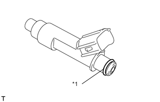
Text in Illustration *1 O-ring
-
Apply a light coat of gasoline or spindle oil to a new O-ring, then install one onto each fuel injector.
-
Apply a light coat of gasoline or spindle oil to the contact surfaces of the fuel delivery pipe and the O-ring of the fuel injector.
-
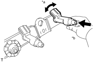
Text in Illustration *a Turn *b Push While turning the fuel injector left and right, install it onto the fuel delivery pipe.
Note
-
Do not twist the O-ring.
-
After installing the fuel injectors, check that they turn smoothly. If not, replace the O-ring with a new one.
-
-
-
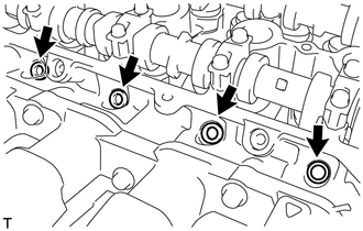
INSTALL INJECTOR VIBRATION INSULATOR
-
Install 4 new injector vibration insulators onto the cylinder head.
-
-
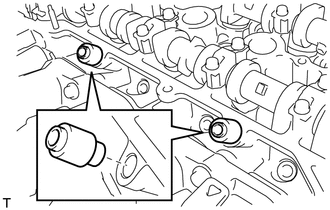
INSTALL NO. 1 DELIVERY PIPE SPACER
-
Install the 2 No. 1 delivery pipe spacers onto the cylinder head.
Note
Install the delivery pipe No. 1 spacer in the correct direction.
-
-
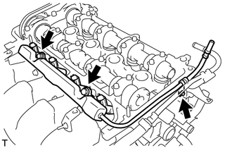
INSTALL FUEL DELIVERY PIPE SUB-ASSEMBLY
-
Provisionally install the fuel delivery pipe sub-assembly with the 4 fuel injectors using the 3 bolts.
Note
-
Do not drop the fuel injectors when installing the fuel delivery pipe sub-assembly.
-
Check that the fuel injectors rotate smoothly after installing the fuel delivery pipe sub-assembly.
-
-
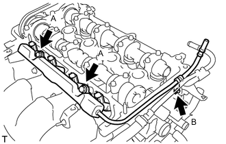
Tighten the 3 bolts to the specified torque.
- Torque:
- 19 N*m { 194 kgf*cm, 14 ft.*lbf }
- for bolt A
- 9.0 N*m { 92 kgf*cm, 80 in.*lbf }
- for bolt B
-
-
INSTALL CYLINDER HEAD COVER SUB-ASSEMBLY
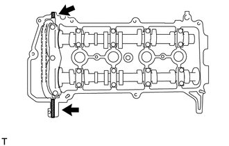
-
Install the gasket onto the cylinder head cover.
-
Apply seal packing to the cylinder head, as shown in the illustration.
Text in Illustration Seal Packing Seal Packing Toyota Genuine Seal Packing Black, Three Bond 1207B or equivalent Note
-
Remove any oil from the contact surface.
-
Install the cylinder head cover sub-assembly within 3 minutes of applying seal packing.
-
Do not start engine for at least 2 hours after the installation.
-
-
Provisionally install the cylinder head cover sub-assembly with the 9 bolts, 2 nuts and 2 seal washers.
-
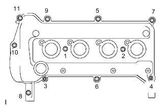
Tighten the 9 bolts and 2 nuts in the sequence shown in the illustration.
- Torque:
- 10 N*m { 102 kgf*cm, 7 ft.*lbf }
-
-
INSTALL VENTILATION VALVE SUB-ASSEMBLY
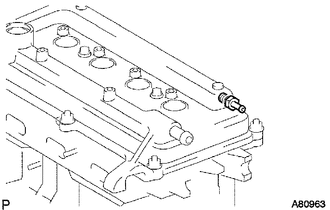
-
Install the ventilation valve onto the cylinder head cover.
- Torque:
- 27 N*m { 275 kgf*cm, 20 ft.*lbf }
-
-
INSTALL CRANKSHAFT POSITION SENSOR
-
Apply a light coat of engine oil to the O-ring on the crankshaft position sensor.
Note
If the O-ring is damaged, replace the crankshaft position sensor.
-
Install the crankshaft position sensor with the bolt.
- Torque:
- 7.5 N*m { 76 kgf*cm, 66 in.*lbf }
-
-
INSTALL OIL FILLER CAP GASKET
-
Install the oil filler cap gasket onto the oil filler cap.
-
-
INSTALL OIL FILLER CAP SUB-ASSEMBLY
-
Install the oil filler cap onto the cylinder head cover.
-
-
INSTALL THERMOSTAT
-
Install a new gasket onto the thermostat.
-
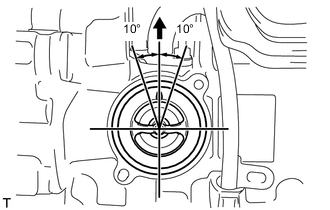
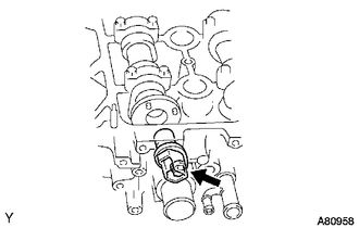
Install the thermostat with the jiggle valve facing upward.
Tech Tips
The jiggle valve may be set within 10° on either side as shown in the illustration.
-
-
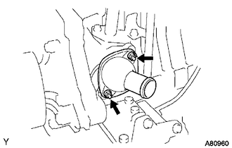
INSTALL WATER INLET
-
Install the water inlet with radiator hose using the 2 nuts.
- Torque:
- 9.0 N*m { 92 kgf*cm, 80 in.*lbf }
-
-
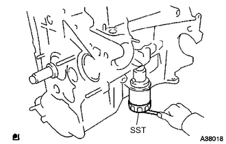
INSTALL ENGINE COOLANT TEMPERATURE SENSOR
-
Provisionally install the engine coolant temperature sensor using a new gasket.
-
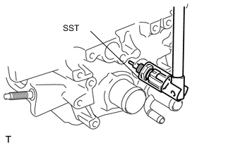
Using SST, tighten the engine coolant temperature sensor.
- SST
- 09817-33190
- Torque:
- 20 N*m { 204 kgf*cm, 15 ft.*lbf }
-
-
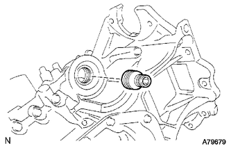
INSTALL ENGINE OIL PRESSURE SWITCH ASSEMBLY
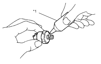
Text in Illustration *1 Adhesive
-
Apply adhesive to the end 2 or 3 threads of the oil pressure switch.
Adhesive Toyota Genuine Adhesive 1324, Three Bond 1324 or equivalent Note
Do not start the engine for at least 1 hour after the installation.
-
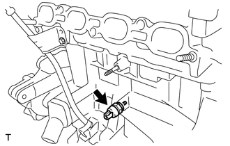
Using a 24 mm deep socket wrench, install the oil pressure switch.
- Torque:
- 15 N*m { 153 kgf*cm, 11 ft.*lbf }
-
-
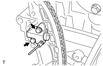
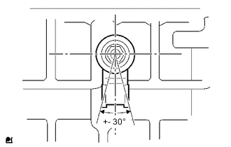
INSTALL KNOCK SENSOR
-
Install the knock sensor with the nut as shown in the illustration.
- Torque:
- 20 N*m { 204 kgf*cm, 15 ft.*lbf }
-
-
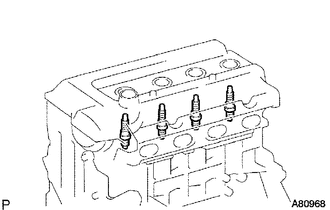
INSTALL SPARK PLUG
-
Using a spark plug wrench, install the spark plugs.
- Torque:
- 18 N*m { 184 kgf*cm, 13 ft.*lbf }
-