FUEL INJECTOR INSTALLATION

PROCEDURE
-
INSTALL INJECTOR VIBRATION INSULATOR
-
Install 4 new injector vibration insulators onto the cylinder head.
-
-
INSTALL NO. 1 DELIVERY PIPE SPACER
-
Install the 2 No. 1 delivery pipe spacers onto the cylinder head.
Note
Install the No. 1 delivery pipe spacers in the correct direction.
-
-
INSTALL FUEL INJECTOR ASSEMBLY
-
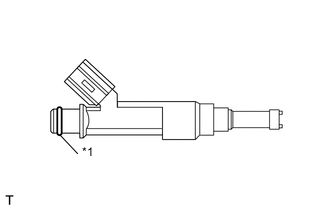
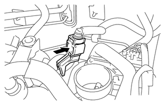
Text in Illustration *1 O-ring Apply a light coat of gasoline or spindle oil to new O-rings, then install one onto each fuel injector assembly.
-
Apply a light coat of gasoline or spindle oil to the contact surfaces of the fuel delivery pipe and the O-ring of the fuel injector assembly.
-
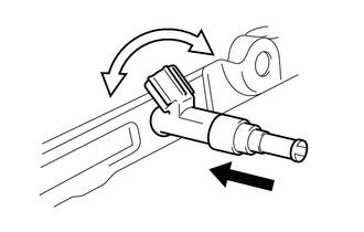
While turning the fuel injector assembly left and right, install it onto the fuel delivery pipe sub-assembly.
Text in Illustration 
Push 
Turn Note
-
Do not twist the O-ring.
-
After installing the fuel injectors, check that they turn smoothly. If not, replace the O-ring with a new one.
Tech Tips
After replacing the fuel injector assembly, perform the "Inspection After Repairs" Click here.
-
-
-
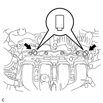
INSTALL FUEL DELIVERY PIPE
-
Install the fuel delivery pipe with the 4 fuel injectors, and then temporarily install the 2 bolts.
Note
-
Do not drop the fuel injectors when installing the fuel delivery pipe sub-assembly.
-
Check that the fuel injector assemblies rotate smoothly after installing the fuel delivery pipe sub-assembly.
-
-
Tighten the 2 bolts to the specified torque.
- Torque:
- 28 N*m { 285 kgf*cm, 21 ft.*lbf }
-
-
CONNECT FUEL TUBE SUB-ASSEMBLY
-
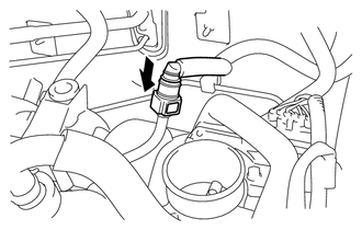
Line up the pipe and connector and push them together until a "click" sound is heard.
Note
-
Check that there are no scratches or foreign objects on the connecting part.
-
If the pipe is difficult to push into the connector, apply a small amount of clean engine oil to the tip of the pipe and reinsert it
-
After connecting, check that the pipe and connector are securely connected by pulling on them.
-
-
-
INSTALL EFI FUEL PIPE CLAMP
-
Install the EFI fuel pipe clamp.
-
-
INSTALL AIR CLEANER CASE SUB-ASSEMBLY
-
Install the air cleaner case sub-assembly with the 2 bolts.
- Torque:
- 7.8 N*m { 80 kgf*cm, 69 in.*lbf }
-
-
INSTALL INLET NO. 1 AIR CLEANER
-
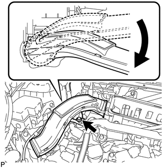
Install the inlet No. 1 air cleaner as shown in the illustration.
-
Tighten the bolt.
- Torque:
- 7.8 N*m { 80 kgf*cm, 69 in.*lbf }
-
-
INSTALL NO. 1 AIR CLEANER HOSE
-
INSTALL AIR CLEANER FILTER ELEMENT SUB-ASSEMBLY
-
Install the air cleaner filter element sub-assembly to the air cleaner case.
-
-
INSTALL AIR CLEANER CAP SUB-ASSEMBLY
-
INSPECT FOR FUEL LEAK
-
INSTALL NO. 1 ENGINE COVER