CYLINDER HEAD GASKET INSTALLATION

PROCEDURE
-
INSTALL CYLINDER HEAD GASKET
-
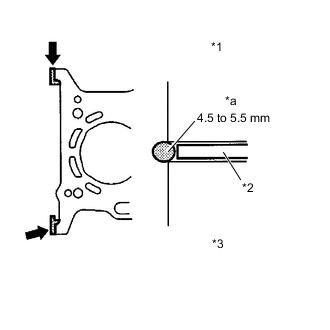
Text in Illustration *1 Cylinder Head Sub-assembly *2 Cylinder Head Gasket *3 Cylinder Block *a Diameter 
Seal Packing Apply a continuous bead of seal packing (Diameter 4.5 to 5.5 mm (0.177 to 0.217 in.)) as shown in the illustration.
Seal Packing Toyota Genuine Seal Packing Black, Three Bond 1207B or equivalent Note
-
Remove any oil from the contact surfaces.
-
Install the oil pump assembly within 3 minutes and tighten the bolts within 15 minutes of applying the seal packing.
-
-

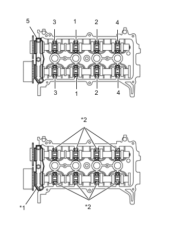
Text in Illustration *a Lot No. Place a new cylinder head gasket on the cylinder block with the Lot No. stamp facing upward.
Note
-
Remove any oil from the contact surfaces.
-
Be sure to place the cylinder head gasket in the correct direction.
-
Do not damage the cylinder gasket when installing the cylinder head sub-assembly onto the cylinder block.
-
-
-
INSTALL CYLINDER HEAD SUB-ASSEMBLY
Tech Tips
The cylinder head set bolts are tightened in 2 successive steps.
-
Install the cylinder head sub-assembly on the cylinder block.
-
Apply a light coat of engine oil to the threads of the cylinder head set bolts.
-
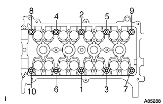
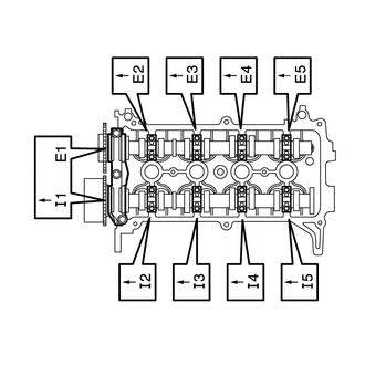
Using 2 successive steps, install and tighten the 10 cylinder head set bolts and plate washers uniformly with an 8 mm bi-hexagon wrench, in the sequence shown in the illustration.
- Torque:
- 29 N*m { 300 kgf*cm, 21 ft.*lbf }
-
Mark the front of the cylinder head set bolt with paint.
-
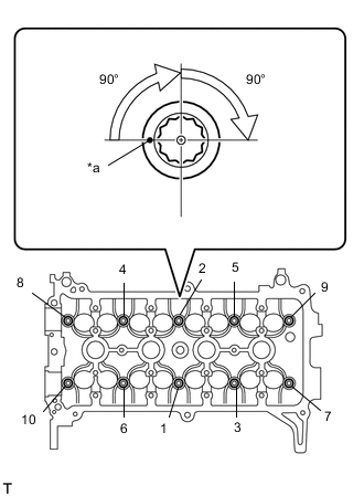
Text in Illustration *a Paint Mark Further tighten the cylinder head set bolts 90° and then an additional 90° as shown in the illustration.
-
Check that the paint mark is now at a 180° angle from the front.
-
-
INSTALL VALVE STEM CAP
-
Apply a light coat of engine oil to the valve stem ends.
-
Install the 16 valve stem caps to the cylinder head sub-assembly.
Note
Do not drop the valve stem caps into the cylinder head sub-assembly.
-
-
INSTALL VALVE LASH ADJUSTER ASSEMBLY
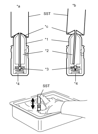
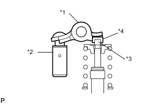
Text in Illustration *1 Plunger *2 Low Pressure Chamber *3 Check Ball *4 High Pressure Chamber *a Correct *b Incorrect *c Taper Part Note
-
Keep the valve lash adjuster assembly free of dirt and foreign matter.
-
Only use clean engine oil.
-
Place the valve lash adjuster assembly into a container filled with engine oil.
-
Insert the tip of SST into the valve lash adjuster plunger and use the tip to press down on the check ball inside the plunger.
- SST
- 09276-75010
-
Squeeze SST and the valve lash adjuster assembly together to move the plunger up and down 5 to 6 times.
-
Check the movement of the plunger and bleed it.
OK Plunger moves up and down. Note
When bleeding the high-pressure chamber, make sure that the tip of SST is actually pressing the check ball as shown in the illustration. If the check ball is not pressed, the high-pressure chamber will not be bled.
-
After bleeding, remove SST. Then, try to press the plunger quickly and firmly by hand.
OK Plunger is very difficult to move. If the result is not as specified, replace the valve lash adjuster assembly.
-
Install the valve lash adjuster assemblies.
Note
Install each valve lash adjuster assembly to the same place it was removed from.
-
-
INSTALL NO. 1 VALVE ROCKER ARM SUB-ASSEMBLY
-
Text in Illustration *1 No. 1 Valve Rocker Arm Sub-assembly *2 Valve Lash Adjuster assembly *3 Valve Stem *4 Valve Stem Cap Apply engine oil to the valve lash adjuster assembly tip and valve stem cap end.
-
Make sure that the No. 1 valve rocker arm sub-assemblies are installed as shown in the illustration.
-
-
INSTALL CAMSHAFT
-
Place the camshaft on the cylinder head sub-assembly with the timing mark on the camshaft timing gear assembly facing upward.
-
Place the No. 2 camshaft on the cylinder head sub-assembly with the timing mark on the camshaft timing sprocket facing upward.
-
Examine the front marks and numbers on the No. 1 camshaft bearing cap and No. 2 camshaft bearing caps and check that the order is as shown in the illustration. Then temporarily tighten the 19 bolts.
-
Text in Illustration *1 No. 1 Bearing Cap *2 No. 2 Bearing Cap Uniformly tighten the bolts in several steps in the sequence shown in the illustration and install the No. 1 camshaft bearing cap and No. 2 camshaft bearing caps.
- Torque:
- No. 1 camshaft bearing cap
- 23 N*m { 235 kgf*cm, 17 ft.*lbf }
- No. 2 camshaft bearing cap
- 13 N*m { 129 kgf*cm, 9 ft.*lbf }
Note
Tighten each bolt uniformly while keeping the camshaft level.
-
-
INSTALL CHAIN SUB-ASSEMBLY
-
INSTALL NO. 1 CHAIN VIBRATION DAMPER
-
INSTALL CHAIN TENSIONER SLIPPER
-
INSTALL NO. 1 CHAIN TENSIONER ASSEMBLY
-
INSTALL NO. 2 CHAIN VIBRATION DAMPER
-
INSTALL OIL PUMP SEAL
-
INSTALL OIL PUMP ASSEMBLY
-
INSTALL V-RIBBED BELT TENSIONER ASSEMBLY
-
INSTALL TRANSVERSE ENGINE ENGINE MOUNTING BRACKET
-
INSTALL ENGINE WATER PUMP ASSEMBLY
-
INSTALL WATER PUMP PULLEY
-
INSTALL CAMSHAFT TIMING OIL CONTROL VALVE ASSEMBLY
-
INSTALL CRANK POSITION SENSOR
-
INSTALL CRANKSHAFT DAMPER SUB-ASSEMBLY
-
INSTALL ENGINE MOUNTING INSULATOR SUB-ASSEMBLY RH
-
INSTALL CYLINDER HEAD COVER SUB-ASSEMBLY
-
INSTALL NO. 1 IGNITION COIL
-
INSTALL GENERATOR BRACKET
-
INSTALL GENERATOR ASSEMBLY
-
INSTALL FAN AND GENERATOR V BELT
-
INSTALL MANIFOLD ABSOLUTE PRESSURE SENSOR
-
Install the manifold absolute pressure sensor with the nut.
- Torque:
- 7.5 N*m { 76 kgf*cm, 66 in.*lbf }
-
-
INSTALL NO. 1 OIL PIPE
-
Install a new 2 gaskets and temporarily install the No. 1 oil pipe with the 2 oil pipe union bolts.
-
Tighten the oil pipe union.
- Torque:
- 36 N*m { 367 kgf*cm, 27 ft.*lbf }
-
-
CONNECT WIRE HARNESS
-
Connect the wire harness with the 2 bolts.
- Torque:
- 8.5 N*m { 87 kgf*cm, 75 in.*lbf }
-
Connect all the wire harnesses and connectors.
-
-
INSTALL NO. 1 WATER BY-PASS PIPE
-
Install the manifold absolute pressure sensor with the nut.
-
Install the No. 1 water by-pass pipe with the 2 bolts and 2 nuts.
- Torque:
- 10 N*m { 102 kgf*cm, 7 ft.*lbf }
-
-
INSTALL EXHAUST MANIFOLD
-
CONNECT OUTLET WATER BY-PASS
-
Connect the outlet water by-pass to the No. 1 water by-pass pipe with the hose clamp.
-
-
INSTALL BOOSTER VACUUM TUBE
-
INSTALL EGR DELIVERY CHAMBER
-
INSTALL ENGINE OIL LEVEL DIPSTICK GUIDE
-
INSTALL ENGINE OIL LEVEL DIPSTICK SUB-ASSEMBLY
-
INSTALL NO. 2 INTAKE MANIFOLD INSULATOR
-
Install the No. 2 intake manifold insulator.
Tech Tips
Securely fit the end of the No. 2 intake manifold insulator under the engine oil level dipstick guide installation tab.
-
-
INSTALL INTAKE MANIFOLD
-
Install a new No. 1 intake manifold gasket onto the intake manifold.
-
Install the intake manifold with the 3 bolts and 2 nuts.
- Torque:
- 30 N*m { 306 kgf*cm, 22 ft.*lbf }
-
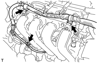
Connect the 3 wire harness clamps shown in the illustration.
-
Install the throttle body connector bracket with the nut.
- Torque:
- 9.0 N*m { 92 kgf*cm, 80 in.*lbf }
-
Connect the throttle body connector.
-
Connect the water by-pass hose to the throttle body with the hose clamp.
-
Connect the No. 2 water by-pass hose to the throttle body with the hose clamp.
-
-
CONNECT UNION TO CONNECTOR TUBE HOSE
-
Connect the union to connector tube hose to the booster vacuum tube with the hose clamp.
-
-
INSTALL EGR VALVE ASSEMBLY
-
INSTALL INLET HEATER WATER HOSE A
-
CONNECT OUTLET HEATER WATER HOSE A
-
INSTALL UNION TO CHECK VALVE HOSE
-
CONNECT FUEL TUBE SUB-ASSEMBLY
-
INSTALL NO. 2 FUEL PIPE CLAMP
-
INSTALL WATER FILLER SUB-ASSEMBLY
-
Install the water filler sub-assembly with the 2 nuts.
- Torque:
- 7.5 N*m { 76 kgf*cm, 66 in.*lbf }
-
Connect the No. 1 radiator hose to the cylinder head with the hose clamp.
-
-
CONNECT RESERVE TANK HOSE
-
Connect the reserve tank hose.
-
-
CONNECT NO. 3 RADIATOR HOSE
-
Connect the No. 3 radiator hose with the hose clamp.
-
-
INSTALL FUEL VAPOR FEED HOSE ASSEMBLY
-
INSTALL VENTILATION HOSE
-
INSTALL AIR CLEANER ASSEMBLY
-
INSTALL BATTERY TRAY
-
INSTALL BATTERY
-
CONNECT CABLE TO NEGATIVE BATTERY TERMINAL
-
Connect the negative (-) cable to the negative (-) battery terminal.
- Torque:
- 5.4 N*m { 55 kgf*cm, 48 in.*lbf }
Note
When disconnecting the cable, some systems need to be initialized after the cable is reconnected Click here.
-
-
ADD ENGINE OIL
-
ADD COOLANT
-
CHECK ENGINE OIL LEVEL
-
INSPECT FOR OIL LEAK
-
INSPECT FOR COOLANT LEAK
-
INSPECT FOR EXHAUST GAS LEAK
-
INSPECT FOR FUEL LEAK
-
INSTALL ENGINE UNDER COVER RH
-
INSTALL FRONT WHEEL RH
- Torque:
- 103 N*m { 1050 kgf*cm, 76 ft.*lbf }