CYLINDER HEAD GASKET REMOVAL

PROCEDURE
-
DISCHARGE FUEL SYSTEM PRESSURE
-
REMOVE BATTERY
-
REMOVE BATTERY TRAY
-
REMOVE FRONT WHEEL RH
-
REMOVE ENGINE UNDER COVER RH
-
DRAIN ENGINE OIL
-
DRAIN COOLANT
-
REMOVE AIR CLEANER ASSEMBLY
-
DISCONNECT NO. 3 RADIATOR HOSE
-
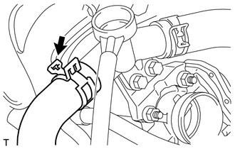
Disconnect the No. 3 radiator hose.
-
-
DISCONNECT RESERVE TANK HOSE
-
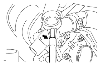
Disconnect the reserve tank hose.
-
-
REMOVE NO. 2 FUEL PIPE CLAMP
-
DISCONNECT FUEL TUBE SUB-ASSEMBLY
-
DISCONNECT UNION TO CHECK VALVE HOSE
-
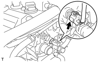
DISCONNECT OUTLET HEATER WATER HOSE A
-
REMOVE WATER FILLER SUB-ASSEMBLY
-
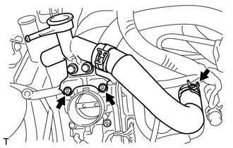
Separate the No. 1 radiator hose from the cylinder head.
-
Remove the 2 nuts and the water filler sub-assembly.
-
-
REMOVE EGR VALVE ASSEMBLY
-
REMOVE INTAKE MANIFOLD
-
REMOVE OIL LEVEL DIPSTICK SUB-ASSEMBLY
-
REMOVE OIL LEVEL GAGE GUIDE
-
REMOVE EGR DELIVERY CHAMBER
-
SEPARATE NO. 4 WATER BY-PASS HOSE
-
SEPARATE NO. 3 WATER BY-PASS HOSE
-
REMOVE BOOSTER VACUUM TUBE
-
DISCONNECT CAMSHAFT POSITION SENSOR CONNECTOR
-
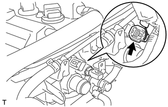
Disconnect the camshaft position sensor connector.
-
-
DISCONNECT ENGINE COOLANT TEMPERATURE SENSOR CONNECTOR
-
Disconnect the engine coolant temperature sensor connector.
-
-
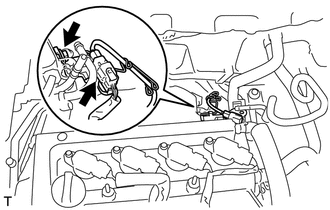
REMOVE WIRING HARNESS CLAMP BRACKET
-
Remove the bolt and separate the wiring harness clamp bracket.
-
Disconnect the heated oxygen sensor connector.
-
-
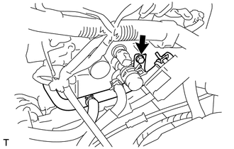
SEPARATE NO. 1 WATER BY-PASS PIPE
-
Remove the bolt and separate the No. 1 water by-pass pipe.
-
-
REMOVE NO. 1 OIL PIPE
-
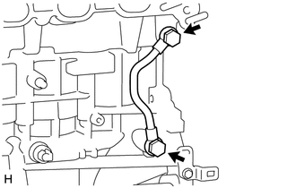
Remove the 2 oil pipe unions, gaskets and No. 1 oil pipe.
-
-
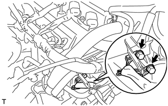
DISCONNECT WIRE HARNESS
-
Remove the 2 bolts and disconnect the wire harness.
-
-
SEPARATE FRONT EXHAUST PIPE ASSEMBLY
-
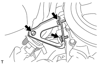
REMOVE MANIFOLD SUPPORT BRACKET
-
Remove the 3 bolts and the manifold support bracket.
-
-
REMOVE FAN AND GENERATOR V BELT
-
REMOVE GENERATOR ASSEMBLY
-
REMOVE NO. 1 IGNITION COIL
-
REMOVE VENTILATION HOSE
-
REMOVE FUEL VAPOR FEED HOSE ASSEMBLY
-
REMOVE INLET HEATER WATER HOSE A
-
REMOVE CYLINDER HEAD COVER SUB-ASSEMBLY
-
REMOVE ENGINE MOUNTING INSULATOR SUB-ASSEMBLY RH
-
REMOVE CRANKSHAFT DAMPER SUB-ASSEMBLY
-
REMOVE CRANKSHAFT POSITION SENSOR
-
REMOVE CAMSHAFT TIMING OIL CONTROL VALVE ASSEMBLY
-
REMOVE WATER PUMP PULLEY
-
REMOVE WATER PUMP ASSEMBLY
-
REMOVE TRANSVERSE ENGINE ENGINE MOUNTING BRACKET
-
REMOVE OIL PUMP ASSEMBLY
-
REMOVE OIL PUMP SEAL
-
REMOVE NO. 1 CHAIN TENSIONER ASSEMBLY
-
REMOVE CHAIN TENSIONER SLIPPER
-
REMOVE NO. 1 CHAIN VIBRATION DAMPER
-
REMOVE CHAIN SUB-ASSEMBLY
-
REMOVE CAMSHAFT
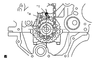
Text in Illustration *1 Oil jet *a Timing Mark Note
When rotating the camshaft with the timing chain removed, rotate the crankshaft counterclockwise 40° from the TDC first, and align the oil jet hole with the paint mark. This prevents the pistons from coming into contact with the valves.
-
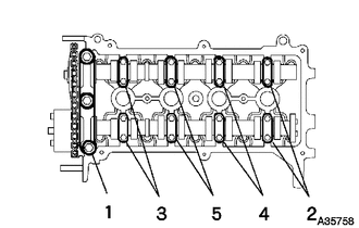
Using several steps, loosen and remove the 19 bearing cap bolts uniformly in the sequence shown in the illustration, and then remove the No. 1 and No. 2 camshaft bearing caps.
Note
Loosen each bolt uniformly while keeping the camshaft level.
-
Remove the No. 2 camshaft and camshaft.
-
-
REMOVE NO. 1 VALVE ROCKER ARM SUB-ASSEMBLY
-
Remove the 16 valve rocker arms.
Tech Tips
Arrange the removed parts in the correct order.
-
-
REMOVE VALVE LASH ADJUSTER ASSEMBLY
-
Remove the 16 valve lash adjusters from the cylinder head.
Tech Tips
Arrange the removed parts in the correct order.
-
-
REMOVE VALVE STEM CAP
-
Remove the 16 valve stem caps.
Tech Tips
Arrange the removed parts in the correct order.
-
-
REMOVE CYLINDER HEAD SUB-ASSEMBLY
-
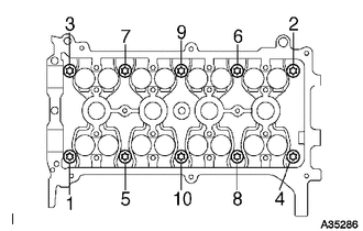
Using several steps, loosen and remove the 10 cylinder head bolts uniformly with an 8 mm bi-hexagon wrench in the sequence shown in the illustration. Remove the 10 plate washers.
Note
-
Do not drop the washers into the cylinder head.
-
Head warpage or cracking could result from removing the bolts in the wrong order.
-
-
-
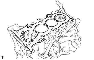
REMOVE CYLINDER HEAD GASKET
-
Remove the cylinder head gasket.
-