CAMSHAFT INSTALLATION
PROCEDURE
-
INSTALL CAMSHAFT TIMING GEAR ASSEMBLY
Note
Install the camshaft timing gear assembly onto the camshaft with the lock pin of the camshaft timing gear assembly released.
-
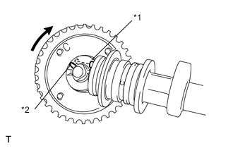
Text in Illustration *1 Straight Pin *2 Groove Put the camshaft timing gear assembly together with the straight pin and key groove misaligned as shown in the illustration.
-
Turn the camshaft timing gear assembly clockwise while pushing it gently toward the camshaft. Push further at the position where the pin fits into the groove.
-
Check that there is no clearance between the gear fringe and the camshaft.
-
Tighten the flange bolt with the camshaft timing gear fixed.
- Torque:
- 64 N*m { 653 kgf*cm, 47 ft.*lbf }
-
Check that the locked in the most retarded position.
-
-
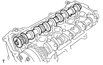
INSTALL CAMSHAFT
-
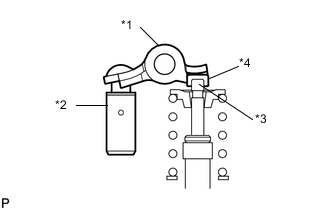
Text in Illustration *1 No. 1 Valve Rocker Arm Sub-assembly *2 Valve Lash Adjuster Assembly *3 Valve Stem *4 Valve Stem Cap Make sure that the valve rocker arms are installed as shown in the illustration.
-
Apply a light coat of engine oil to the camshaft and camshaft journals.
-
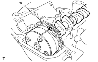
Text in Illustration *a Paint Mark *b Timing Mark Install the chain onto the camshaft timing gear with the paint mark and the timing mark aligned as shown in the illustration.
-
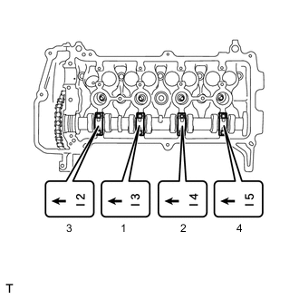
Examine the front marks and numbers on the No. 2 camshaft bearing caps and check that the sequence is as shown in the illustration. Then uniformly tighten the bolts, in several steps, in the sequence shown in the illustration.
- Torque:
- 13 N*m { 129 kgf*cm, 9 ft.*lbf }
Note
Tighten each bolt uniformly while keeping the camshaft level.
-
-
INSTALL NO. 2 CAMSHAFT
-
Text in Illustration *1 No. 1 Valve Rocker Arm Sub-assembly *2 Valve Lash Adjuster Assembly *3 Valve Stem *4 Valve Stem Cap Make sure that the valve rocker arms are installed as shown in the illustration.
-
Install the No. 2 camshaft.
-
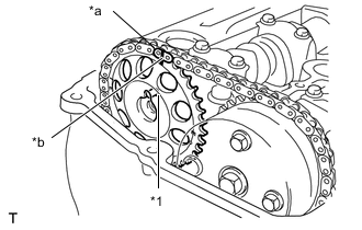
Text in Illustration *1 Pin *a Paint Mark *b Timing Mark Hold the chain and align the timing mark on the camshaft timing sprocket with the paint mark of the chain sub-assembly.
-
Align the alignment pin hole in the camshaft timing sprocket with the alignment pin of the No. 2 camshaft, and install the sprocket onto the No. 2 camshaft.
-
Temporarily install the bolt.
-
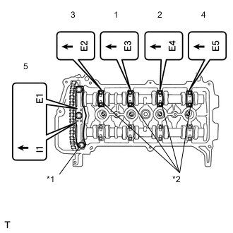
Text in Illustration *1 No. 1 Bearing Cap *2 No. 2 Bearing Cap Examine the front marks and numbers on the No. 1 camshaft bearing cap and No. 2 camshaft bearing caps and check that the order is as shown in the illustration. Then uniformly tighten the bolts, in several steps, in the sequence shown in the illustration.
- Torque:
- 13 N*m { 129 kgf*cm, 9 ft.*lbf }
- for No. 2 bearing cap
- 23 N*m { 235 kgf*cm, 17 ft.*lbf }
- for No. 1 bearing cap
Note
Tighten each bolt uniformly while keeping the camshaft level.
-
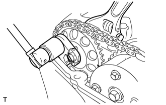
While holding the No. 2 camshaft with a wrench, tighten the bolt.
- Torque:
- 64 N*m { 653 kgf*cm, 47 ft.*lbf }
Tech Tips
-
Connect the torque wrench and the union nut wrench properly so that they form a straight line when using them.
-
Use the formula to calculate special torque values for situations where a union nut wrench is combined with a torque wrench Click here.
-
Remove the bar from the timing chain tensioner.
-
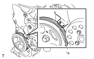
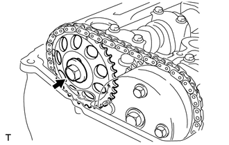
Text in Illustration *a Timing Notch Turn the crankshaft damper and align the timing notch with the timing mark "0" of the oil pump.
-
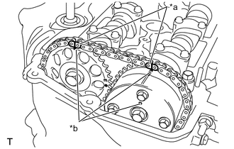
Text in Illustration *a Paint Mark *b Timing Mark Check that all the pairs of timing marks are aligned.
-
Apply adhesive to 2 or 3 threads of the screw plug end.
Adhesive Toyota Genuine Adhesive 1324, Three Bond 1324 or equivalent -
Using an 8 mm (0.31 in.) hexagon wrench, install the screw plug.
- Torque:
- 15 N*m { 153 kgf*cm, 11 ft.*lbf }
Note
Install the bolt within 3 minutes of applying adhesive.
-
-
INSTALL NO. 2 CHAIN VIBRATION DAMPER
-
Install the No. 2 chain vibration damper with the 2 bolts.
- Torque:
- 9.0 N*m { 92 kgf*cm, 80 in.*lbf }
-
-
INSTALL ENGINE MOUNTING INSULATOR SUB-ASSEMBLY RH
-
INSTALL CYLINDER HEAD COVER SUB-ASSEMBLY
-
CONNECT FUEL VAPOR FEED HOSE ASSEMBLY
-
CONNECT VENTILATION HOSE
-
INSTALL NO. 1 IGNITION COIL
-
INSPECT FOR OIL LEAK
-
INSTALL ENGINE UNDER COVER RH