CAMSHAFT REMOVAL
PROCEDURE
-
REMOVE ENGINE UNDER COVER RH
-
REMOVE NO. 1 IGNITION COIL
-
DISCONNECT VENTILATION HOSE
-
DISCONNECT NO. 2 VENTILATION HOSE
-
REMOVE CYLINDER HEAD COVER SUB-ASSEMBLY
-
REMOVE FAN AND GENERATOR V BELT
-
REMOVE ENGINE MOUNTING INSULATOR SUB-ASSEMBLY RH
-
REMOVE NO. 2 CAMSHAFT
Text in Illustration *a Alignment Mark Note
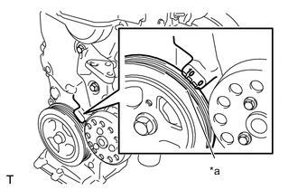
When rotating the camshaft with the timing chain removed, rotate the crankshaft damper counterclockwise 40 ° from the TDC and align the timing notch with the alignment mark of the timing chain cover to prevent the pistons from coming into contact with the valves.
-
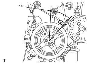
Set the No. 1 cylinder to TDC/compression.
-
Text in Illustration *a Timing Notch Turn the crankshaft damper, and align the timing notch with the timing mark "0" of the oil pump.
-
Text in Illustration *a Timing Mark Check that both timing marks on the camshaft timing sprocket and camshaft timing gear are facing upward, as shown in the illustration.
Tech Tips
If not, turn the crankshaft 1 complete revolution (360°) and align the marks as above.
-
-
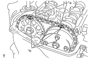
Text in Illustration *a Paint Mark *b Timing Mark Place paint marks on the chain where it touches the timing marks on the camshaft timing sprocket and the camshaft timing gear.
-
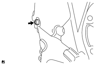
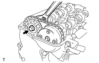
Using an 8 mm (0.31in.) hexagon wrench, remove the screw plug.
-
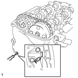
Text in Illustration *1 Stopper Plate Insert a screwdriver into the service hole in the chain tensioner to pull the stopper plate of the chain tensioner upward.
-
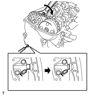
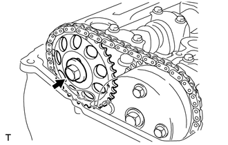
Text in Illustration *1 Plunger Using a wrench, rotate the No. 2 camshaft clockwise to push in the plunger of the chain tensioner.
-
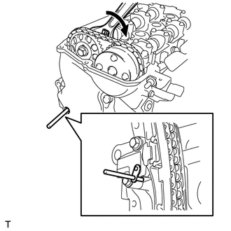
Remove the screwdriver from the service hole, then align the hole the stopper plate with the service hole and insert a 3 mm (0.12 in.) diameter bar into the holes to hold the stopper plate.
Tech Tips
-
Fix the stopper plate using the bar while rotating the camshaft right and left slightly.
-
Hold the bar with tape so that the bar does not come off.
-
-
Using a wrench, hold the hexagonal lobe of the No. 2 camshaft and remove the flange bolt.
-
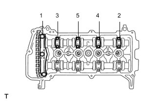
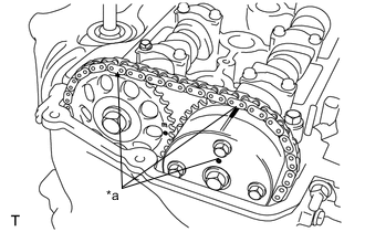
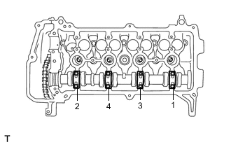
Using several steps, loosen and remove the 11 bearing cap bolts uniformly in the sequence shown in the illustration, then remove the No. 1 and No. 2 camshaft bearing caps.
Note
Loosen the bolts uniformly while keeping the camshaft level.
-
Remove the flange bolt and remove the camshaft timing sprocket.
-
Remove the No. 2 camshaft.
-
-
REMOVE CAMSHAFT
-
Using several steps, loosen and remove the 8 bearing cap bolts uniformly in the sequence shown in the illustration, then remove the No. 2 camshaft bearing cap.
Note
Loosen each bolt uniformly while keeping the camshaft level.
-
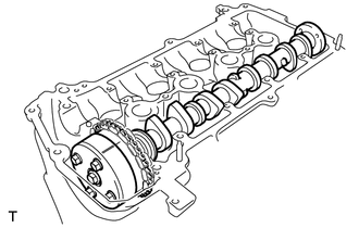
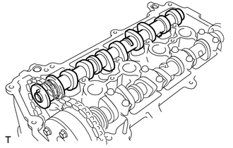
Hold the chain by hand, and remove the camshaft and the camshaft timing gear assembly.
-
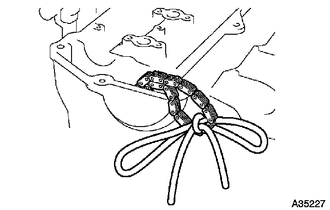
Tie the chain with a piece of string as shown in the illustration.
-
-
REMOVE CAMSHAFT TIMING GEAR ASSEMBLY
-
Clamp the camshaft in a vise and confirm that it is locked.
Note
Do not damage the camshaft.
-
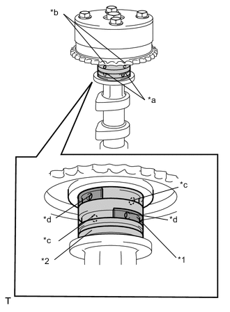
Text in Illustration *1 Rubber Piece *2 Vinyl Tape *a Advance Side Path *b Retard Side Path *c Open *d Close Cover the 4 oil paths of the cam journal with tape as shown in the illustration.
Tech Tips
One of the 2 grooves located on the cam journal is for retarding cam timing (upper) and the other is for advancing cam timing (lower). Each groove has 2 oil paths. Plug one of the oil paths for each groove with a piece of rubber before wrapping the cam journal with the tape.
-
Puncture the tape covering the advance oil path and the retard oil path on the opposite side from the advance oil path.
-
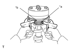
Text in Illustration *a Advance Side Path *b Retard Side Path Apply air at about 150 kPa (1.5 kgf*cm2) pressure into the 2 broken paths (the advance side path and the retard side path).
Note
Cover the paths with a piece of cloth to prevent oil splashes.
-
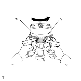
Text in Illustration *a Advance Side Path *b Retard Side Path *c Hold Pressure *d Decompress Confirm that the camshaft timing gear assembly revolves in the timing advance direction when the air pressure on the timing retard path is reduced.
Tech Tips
The lock pin is released, and the camshaft timing gear revolves in the advance direction.
-
When the camshaft timing gear reaches the most advanced position, release the air pressure on the timing retard side path, and then release the air pressure on the timing advance side path.
Note
The camshaft timing gear assembly occasionally shifts to the retard side abruptly, if the air pressure on the advance side path is released first. This often results in the breakage of the lock pin.
-
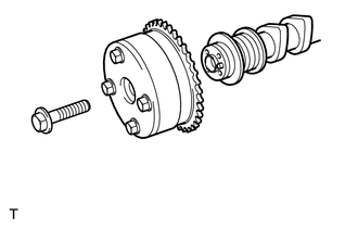
Remove the flange bolt and remove the camshaft timing gear assembly.
Note
-
Do not remove the other 4 bolts.
-
When reusing the camshaft timing gear, unlock the lock pin inside the camshaft timing gear first.
-
-